490
June 2014
PHOTOGRAMMETRIC ENGINEERING & REMOTE SENSING
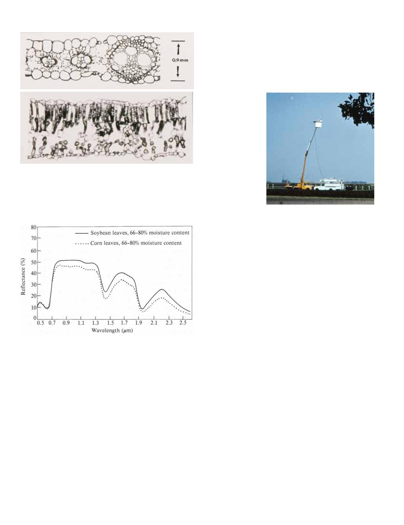
crops and soils (Figure 12). Analysis of the DK-2 spectral data
and the field spectroradiometer data proved to be crucial in
learning how to interpret the multispectral data obtained from
aircraft and eventually, from satellites. The knowledge thus
gained played a key role in the recommendations that sever-
al of us on the LARS staff provided to NASA concerning the
number and spec-
tral location of the
wavelength bands to
be incorporated into
ERTS-1 (i.e., Land-
sat-1) and later, the
Landsat
Themat-
ic Mapper scanner
systems. I believed
then, and still do,
that
understand-
ing the spectral re-
flectance of various
types and conditions
of vegetation and
soils is critical for
effective interpreta-
tion and analysis of
multispectral scan-
ner data.
E
arly
M
ethods
for
I
nterfacing with
M
ultispectral
S
canner
D
ata
In November 1966, shortly after LARS was founded, an IBM
360/Model 44main-frame computer was obtained and installed.
This was only the second machine of this model to be installed
anywhere in the country. The main CPU (Central Processing
Unit) was huge, standing about head-high, was about 10 feet
long and 4 feet wide, and we loaded data into it via large 7-track
tapes and/or computer punch cards (Figure 13). It had no mon-
itor or display capability, so visual displays of remote sensor
data were limited to the line-printer paper printouts discussed
previously. We would often use marker pens and color the dif-
ferent symbols to provide a “color image”, and use this for our
analysis. One might think that there should have been a better
way to do this, but computer monitors such as we know to-
day were simply not available – they hadn’t been invented yet!
Some sort of monitor or display device was clearly needed. Dis-
cussions with NASA and IBM resulted in a collaborative effort
to develop a digital display device to use with remotely sensed
data. NASA contributed $500,000, and IBM matched it with
another $500,000. This first digital display unit, developed by
IBM and installed at LARS in early 1971, had a black-and-
white screen -- not very large; only about 12 by 15 inches – and
a “light pen” that was connected to the display with a fiber
optic cord (Figure 14). The analyst simply pressed the light
pen against the glass screen of the display and the pixel under
the light pen would be high-lighted, thus allowing the analyst
Figure 10. Cross sections of a corn leaf (top) and a soybean leaf (bottom)
[from: Hoffer, 1978]. Corn is a monocot species of plant, having a compact
mesophyll, whereas soybeans are a dicot with dorsiventral mesophyll. The
long tubular cells in the upper half of the soybean leaf provided a significant-
ly higher reflectance in the near infrared wavelengths, as shown in Figure
11. The dark specks in these cross sections are chlorophyll.
Figure 11. DK-2 Spectral reflectance of corn and soybean leaves of the same
range of moisture content (from: Hoffer and Johannsen, 1969).
cross-section data, provided some significant knowledge con-
cerning the potential for spectrally separating various cover
types (Figure 11). These DK-2 spectral data also provided a
better understanding concerning reasons for variations in the
spectral response of various crops, such as what is happening
(spectrally) when vegetation becomes diseased or stressed be-
cause of drought conditions. However, the analysis of spectral
reflectance of individual leaves or soil samples was not ade-
quate for truly understanding the reflectance of the combina-
tion of vegetation and soil that is recorded by an individual
pixel of multispectral scanner data. This led to a significant
amount of research using a field spectroradiometer operated
from a “cherry picker” or utility truck and an associated in-
strument van, thereby enabling spectral data to be collected
in a natural environment over small, well known targets of
Figure 12. Field spectroscopy system, consisting
of a field spectroradiometer operated from
the “cherry-picker” bucket and an instrument
van for recording the data (from: LARS Staff,
1968).


