PHOTOGRAMMETRIC ENGINEERING & REMOTE SENSING
February 2015
91
From the 40’s to the 80’s RAS often worked for the
Department of Agriculture, the Forestry Service, and
large paper companies that needed thousands of square
miles of woodlands flown annually. These projects
included hundreds of flight lines and thousands of images.
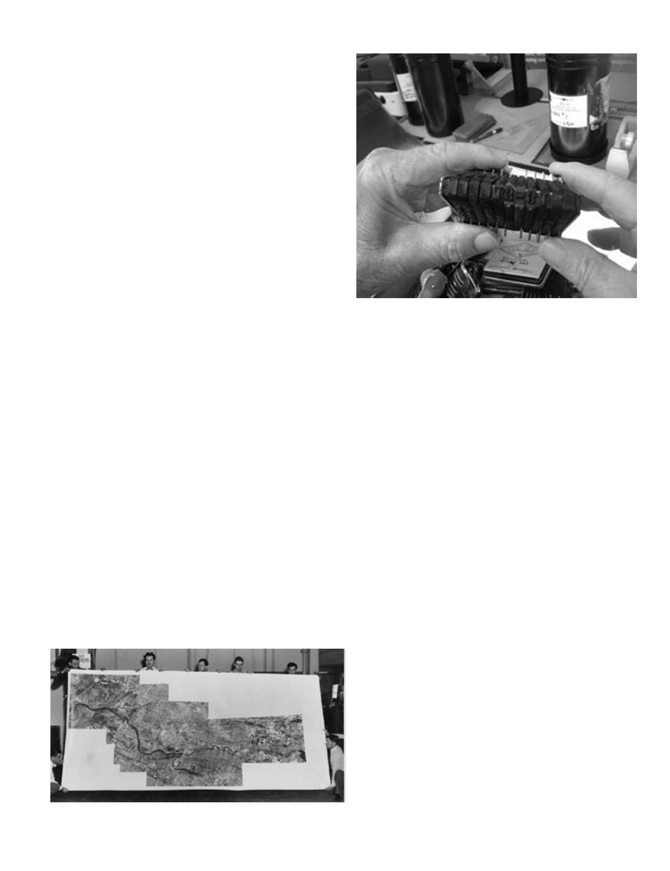
Jack was in charge of developing the aerial film and hand-
stamping each negative, in ink, with a unique mission
code and image number for easy identification, Figure 1.
Jack also produced the 9”x9” contact prints that are still a
common deliverable throughout the industry.
“We used Logatronics auto dodging/
burning enlargers to even out the shades”
— Jack
Dodging and burning are terms used in photography for a
technique used during the printing process to manipulate
the exposure of a selected area(s) on a photographic
print, deviating from the rest of the image’s exposure.
During the developing process of a print from a film
negative, dodging decreases the exposure to areas of
the print that the photographer wishes to be lighter,
while burning increases the exposure to areas of the print
that should be darker.
The process that was used to develop and enlarge photos
was a basic one. Jack would take a developed picture and
crop around the area he wanted to enlarge with black
plastic strips. Then, he’d place the aerial negative into
a large glass frame and slide it into the back of a large
format bellows projection camera that was mounted on 20
ft. long rails. Jack would then expose this projected image
on to photographic paper mounted on an 8 ft. x 20 ft.
movable easel and hand-develop it with Kodak developer,
hypo-clearing agent and, finally, a fresh water bath. In
much the same way that Jack produced the contact prints,
he also produced the thick glass plates that Robinson’s
photogrammetrists would use in their Kelsh, PG-2 and
Stereometrograph mapping instruments.
Aerial photography is used for engineering design,
survey and general mapping projects. Although completely
digital today, the basic photogrammetric process has not
varied that much since the early days. The photography
is taken from an aircraft that is flying at an altitude
necessary to fulfill the project requirements of accuracy
and cost. Currently, the process is similar to the one
Jack used to follow in the early years. However, they
have additional technology that helps with accuracy and
production time.
The surveyor establishes horizontal and vertical control
in the desired project datum, Photo Control Points are
obtained by either
“pre-targeting
“or
“photo picks”,
Aerial
photos are registered to the project control and adjusted
together through a complex least squares adjustment
called
“Aero-Triangulation”.
The original 9”x9” aerial
negatives are “
scanned”
into a high resolution digital
environment; color photo scan files can be as large as 1.5
GB file size for a 9”x 9” format.
A photogrammetrist specialist called a “
compiler”
uses
a specialized optic and software system to
“compile”
the
controlled photo images into a mapping product. This is
accomplished by a combination of manual 3D
“plotting”
and software applications. A compiler must be able to see
in
“3D”
; only about 10% of the population has this abili-
ty. The CAD editor takes the
“compiled”
map and refines
it further to produce a final map. This includes
:
Contour
Labels, Feature Labels, Planimetric Symbology
(i.e., tele-
poles, signs), Line
Styles
(curb line, building line and
contour line),
Legend, and Border/Title Block/Coordinate
Grid etc.
Figure 1. Stamp used to identify images.
Hand-assembled photo mosaics.


