258
April 2017
PHOTOGRAMMETRIC ENGINEERING & REMOTE SENSING
CASE II — C
orridor
S
urvey
U
sing
S
mall
UAS
S
urrogate
S
ystem
Although we operate the fleet of UAS illustrated in Figure 1,
we devised a system that mimics the operation of the UAS
using manned aircraft. Even with PART107 of the new FAA
regulations, we are still restricted from flying over people
who are not participating in operating the UAS. To overcome
this restriction, Woolpert manufactured a small pod to
accommodate a payload that resembles the one on board a
small UAS. We called it a UAS-surrogate and later it was
officially given the name “Renaissance.” In order to evaluate
UAS product accuracy over highways, we would have to
deploy the Renaissance for the evaluation, as we are not
restricted by the FAA rules to fly over busy highways using
a manned aircraft as it is the case with UAS. The pod of the
Renaissance is mounted on the belly of a Cessna 182, Figure
8. The flight was conducted over a 1.3-mile stretch of County
Line Road in Dayton, Ohio.
CASE II — G
round
C
ontrol
and
C
heckpoints
N
etwork
Our team of surveyors established a network of ground control
and checkpoints needed for the study. A total of 38 well-
defined points were surveyed to an accuracy of RMSE
x,y,z
=
0.1 feet. Figure 9 illustrates the ground/checkpoints surveyed
for this evaluation.
CASE II — T
he
I
maging
S
ystem
The payload on the Renaissance includes imaging and geo-
location sensors. The imaging sensor is NIKON D800E,
equipped with a lens with an 85mm focal length. The sensor
contains around 36 million pixels (7,360 × 4,912 pixels), with
dimensions of 36×24mm. The configuration of the lens and
the sensor results in a FOV of 23.85x16 degrees.
CASE II — F
light
D
esign
Five parallel flight lines in the north-south direction were
flown from an altitude of 1,100 feet AGL, resulting in
image ground resolution (GSD) of 2.0cm (see Figure 9). The
additional three short east-west lines only were flown to
cover Woolpert headquarters.
CASE II — D
ata
P
rocessing
and
P
roduct
G
eneration
The imagery was processed following the same procedure and
processing software used for Case I.
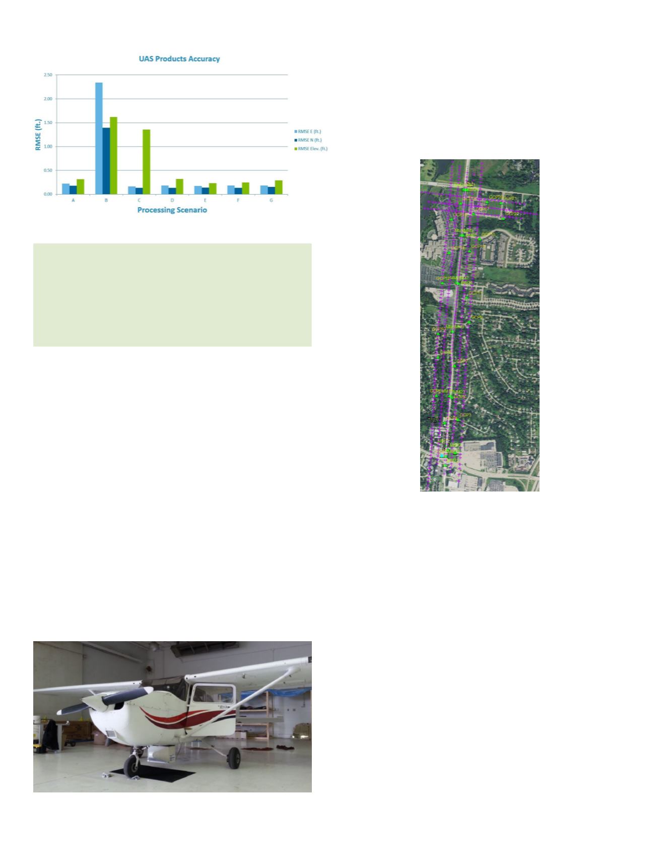
Figure 7: Horizontal and vertical accuracy from UAS products, Case I.
Figure 8: Podded Renaissance system.
“In order for them to meet a 1cm vertical accuracy, their ground
control should be surveyed to an accuracy of 0.25cm or better,
according to the ASPRS Positional Accuracy Standards
for Digital Geospatial Data. Such tight accuracy is hard if
not impossible to meet using current GPS-based surveying
techniques.”
Figure 9: Flight layout and ground controls/checkpoints network for Case II (purple plus
sign = photo center, green triangle = control/checkpoint).


