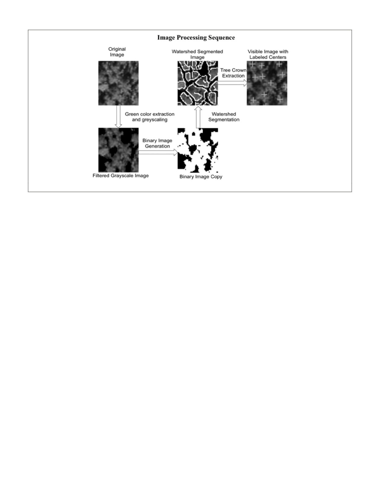
Image processing starts by discarding non-green pixels
(i.e., non-vegetation) using a simple color contrast threshold
approach. A Gaussian disk filter with diameter equal to the
smallest expected crown diameter, in pixels, is then used for
denoising. The resultant color image is then converted to a
grayscale image with 8-bit resolution, and then a copy binary
image is created to calculate the Euclidean distance transform
for all crown objects in the image.
The next step involves applying watershed segmentation
to the 8-bit grayscale image with the distance transform as
input (Bleau and Leon, 2000). The purpose of the distance
transform and watershed segmentation is to delineate individ-
ual tree crowns or segment any cluster of treetops into their
constituent trees. This step is necessary in the case of dense
forests that have touching tree crowns.
Following the segmentation step, an image is produced
that contains delineated objects representing tree crowns of
various sizes. Crowns with diameters of less than a prede-
termined threshold are discarded. For the purposes of our
project and considering the sizes of tree crowns in our test
data, a threshold of 2 m was used. This is a measure against
false positives (underbrush).
The remaining crown objects are subsequently analyzed to
estimate their centers by calculating the Euclidean centroid
of each delineated object. With center pixel coordinates
(x, y)
of each valid crown obtained, relative pixel coordinates are
indexed and mapped to the absolute global positions using
global coordinates of any of the four georeferenced corners of
the original image. The final product is a constellation map
composed of the absolute horizontal coordinates (northing and
easting) of the centroid of each detected and validated crown.
A walkthrough of the algorithm using a sample overhead
image is shown in Figure 2. The overhead image is of a pine
forest located northeast of Lake Mize in Florida. The image is
an orthophoto with 0.3 m resolution and estimated accuracy
of 2.1 m
RMS
(Source: USGS).
There are some general considerations as well as con-
straints to the performance of the tree crown delineation and
center estimation algorithm:
1. Accuracy of estimated tree centers depends on the
view angle (perspective) of the image. Therefore for
best results and to reduce the effect of parallax, the area
of the forest of interest needs to ideally be at the nadir
of the image.
2. Not all stems visible in lidar are visible from the over-
head image and vice versa. Such limitation is inevi-
table in dense forest environments due to the nature of
growth of trees as well as the field-of-view and perspec-
tive of the different sensors involved.
3. The average diameter of a tree crown is recommended
to be at least an order of magnitude larger than the pixel
resolution of the input image (Wang
et al.
, 2004). For ex-
ample, the pixel resolution of an input image needs to be
around 0.3 m in order to adequately detect 3 m crowns.
Tree Stem Identification, Extraction and Center Estimation from
Rover Lidar Data
The second component of the algorithm is designed to sepa-
rate the ground plane from points comprising tree stems and
estimate locations of the centers of stems. The algorithm dis-
cussed in this section draws heavily upon prior work by Matt
McDaniel (McDaniel, 2010) and (McDaniel
et al.
, 2012).
To perform localization, a 360
°
panoramic lidar scan
should be taken at each pose for comparison to the stem con-
stellation map generated from overhead imagery. As discussed
earlier, the algorithm has three main functions: (a) filter out
and discard points comprising the ground plane, (b) extract 3
D
points that comprise tree stems by fitting primitives to candi-
date clusters of points situated above ground, and (c) Calcu-
late centers of 3
D
transects of stems to estimate stem centers.
For the first step, the ground plane is estimated in order to
constrain the search space and facilitate the search for can-
didate tree stems. This step is divided into two main stages.
The first stage is a local height-based filter that determines
the lowest points of every vertical column of data in order
to roughly locate the ground plane. In practice, this elimi-
nates a large percentage of non-ground points from further
consideration. The second stage is a Support Vector Machine
(
SVM
) classifier that combines eight geometric measures (the
classification features) to accurately determine which of the
remaining points belong to the ground plane.
Figure 2. Example Showing Tree Center Estimation Using a Sample Overhead Image of a Pine Forest.
PHOTOGRAMMETRIC ENGINEERING & REMOTE SENSING
November 2015
841


