The main function of the
ICP
algorithm is to estimate the
horizontal translation and rotation parameters required to
fit the input maps together. More precisely, the tree center
constellation map derived from the overhead image is treated
as the baseline upon which the lidar-based tree center map
is matched to. This approach is chosen because the map
obtained from the overhead image is usually larger than the
local map generated from the lidar dataset.
The core
ICP
implementation follows the 2D rigid Besl-
McKay (point-to-point) framework given below (Besl and
McKay, 1992):
arg
,
min
p q
i
N
i
i
N
R p t q
∈
=
=
× + −
∑
R
2
1
1
2
E
(2)
where
E
is the mean squared distance error between both
maps;
R
and
t
is the rotation matrix and translation vector
respectively;
p
and
q
are points in the tree center maps from
the lidar and overhead image datasets, respectively.
N
is the
total number of points in the lidar tree center map. A match is
found by determining the minimum of the error expression
E
.
This formulation is adequate for noiseless maps that do not
contain outliers. However, standard
ICP
will provide skewed
results if noisy data is used. Other algorithms such as Gauss-
ian and Trimmed
ICP
require the same number of points for
both sets of input data. This is not always possible due to the
variability of features observed in aerial imagery compared
to those seen in ground data. A variant of
ICP
was therefore
developed for the purposes of this project that can work with
different input data sizes and is robust against moderate pres-
ence of outliers. The algorithm is inspired by other robust
registration algorithms such as Gaussian
ICP
, Trimmed
ICP
and
RANdom SAmple Consensus (
RANSAC
) (Fischler and Bolles,
1981). In essence, the algorithm calculates the Euclidean
distance error between the input data and incorporates it into
an iterative probabilistic best match search scheme. The
ICP
algorithm uses the rover pose estimates as input for compari-
son to its matching results and attempts to minimize the error
between them. To minimize the error in the presence of outli-
ers, the algorithm systematically discards suspicious outliers
by iterating the matching process using randomly selected
points from the lidar generated map. An outline of the logic
followed by the algorithm is given in Table 2.
It is noted that due to the local minima convergence prop-
erty of
ICP
, the rover pose is used as input in order to avoid
local convergence. Therefore, the best estimate of the location
of the rover is given to
ICP
as a seed upon which matching is
initiated. In cases where large jumps are observed in position
estimates, the latest estimate with the least deviation from the
average is selected.
Testing and Results
Study Area
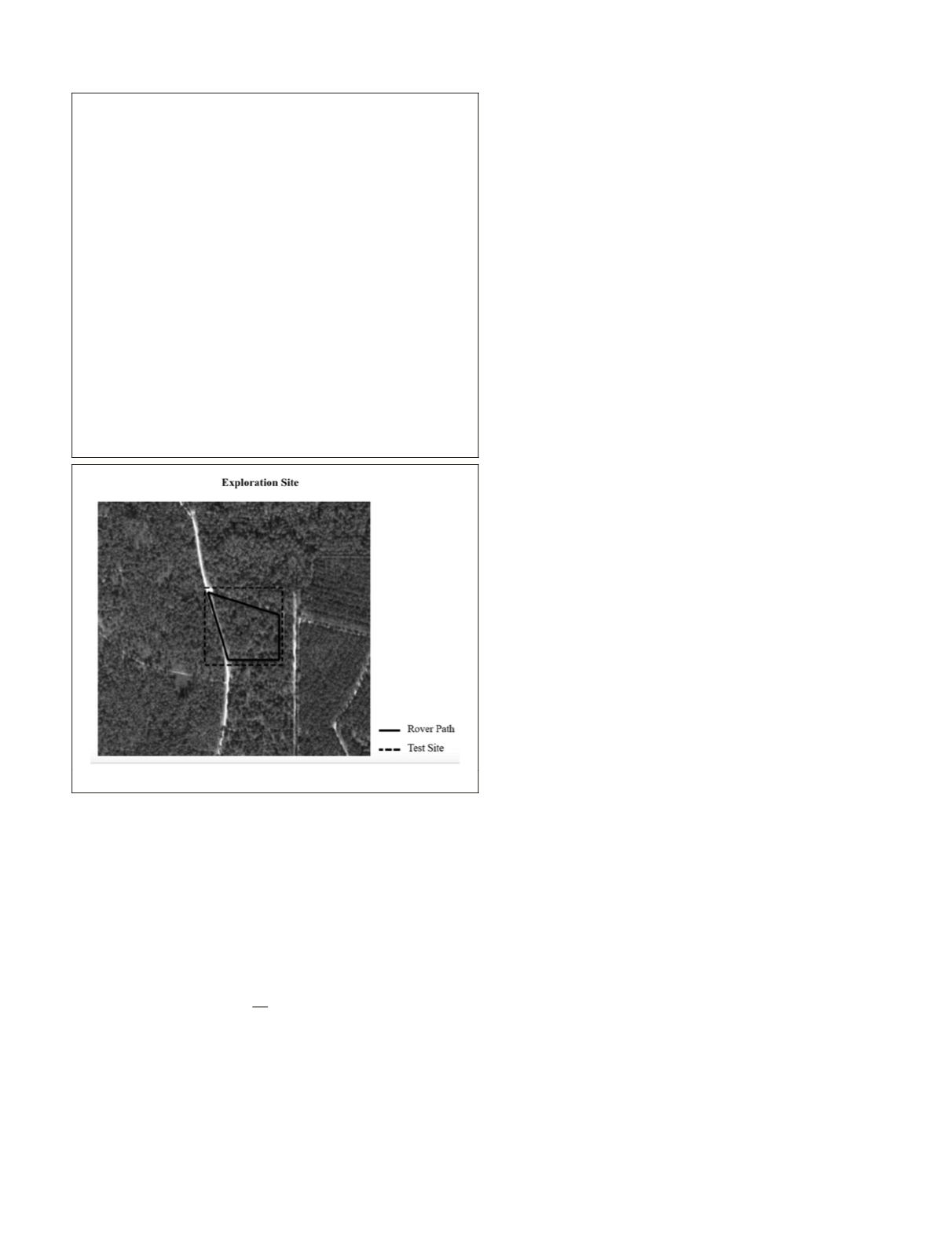
Survey-grade lidar data was collected at a test site located
northeast of Lake Mize in Florida (Coordinates: N29.738°,
W82.216°). The area includes relatively flat terrain. The data
was acquired by a survey grade Leica ScanStation-2 lidar that
was integrated with a high accuracy differential
GPS
system.
For the purposes of this study, the georeferenced lidar dataset
served as the ground reference data upon which the per-
formance of the localization algorithm and its components
were tested against. The lidar was placed at multiple survey
stations within the area bounded by the rectangular box in
Figure 5. The area is approximately 110 m × 110 m and the
lidar dataset was collected with an average spatial resolution
of approximately 5 cm (on ground). The area is exclusively
comprised of mature pine trees with moderate to dense
underbrush and with non-uniform distribution, making this
an appealing test site in terms of different tree geometries.
It is noted that 561 tree stems were manually identified and
labeled in the lidar data within the bounded area.
Data Preparation and Properties
Three high-resolution orthorectified images of the test site
were acquired from the USGS. The images were provided in
GeoTiff format. Table 3 summarizes the key properties of the
acquired imagery and lidar data such as size, resolution, and
accuracy. It is noted that Aerial Image 1 and Aerial Image 2
were taken of the same area but with different sensors and on
different dates. Aerial Image 2 was selected for our tests due
to its higher resolution and the close proximity of the test site
to the nadir of the image, thus reducing parallax.
Component Testing
To assess the overall accuracy of the localization algorithm,
the algorithms’ tree crown identification and matching com-
ponents were tested separately using the same data acquired
from the Lake Mize site. This section focuses on demonstrat-
ing the performance of these two components while the next
Section discusses the tests and their results from running the
full localization algorithm.
T
able
2. A R
obust
A
lgorithm
for
P
oint
-
to
-P
oint
M
atching
of
T
ree
C
enter
M
aps
Input:
The stem constellation set
M
, the lidar stem set
S
and
the rover pose
x
.
Output:
The optimal transformation parameter θ that best
aligns
S
to
M
.
Begin:
•
Place the origin of the search space at the current best
estimate of the location of the rover based on pose
x
.
Repeat
•
Place the set at the top left corner of the search space
(origin).
•
Invoke standard ICP to optimize the objective function
E
.
•
Compute the new estimated rover position based on the
match between
S
and
M
.
•
If Euclidean distance error
E
between new and previous
vehicle positions is not below threshold:
o
Randomly select one stem point from
S
and
temporarily set aside.
o
Update
S
to include one less stem point that was
just selected and prepare to discard if next iteration
results in less error
E
or keep if error increases.
Until
distance error
E
is below predefined threshold.
End
Figure 5. Test Site Northeast of Lake Mize (Source: USGS).
PHOTOGRAMMETRIC ENGINEERING & REMOTE SENSING
November 2015
843


