Theory/Calculation
To assist with using the stitched images to match debris-field
objects with known man-made objects,
CAD
models of the
front and rear landing gear were created based on measure-
ments taken from an extant Lockheed Electra Model 10E, and
the rear tire was modeled using dimensions specified on the
Earhart aircraft inspection report, which identified the rear
wheel as a Goodyear 3TWA with a four ply Goodyear 16×7
tire. The stitched image was placed as a background image
within SolidWorks. These
CAD
models
were then visually superimposed on the
stitched images to match the pose of the
features in the underwater video. The
diameter of the rope was then measured
within SolidWorks, assuming that the rope
and the features lay in the same plane rela-
tive to the mosaic, which defined the rela-
tive coordinate system relative to which
measurements were made. Using the
CAD
rear landing gear as a size reference, the
rope was measured at five locations and
was identified to have a diameter of 15.5
mm, with a standard deviation of 0.3 mm
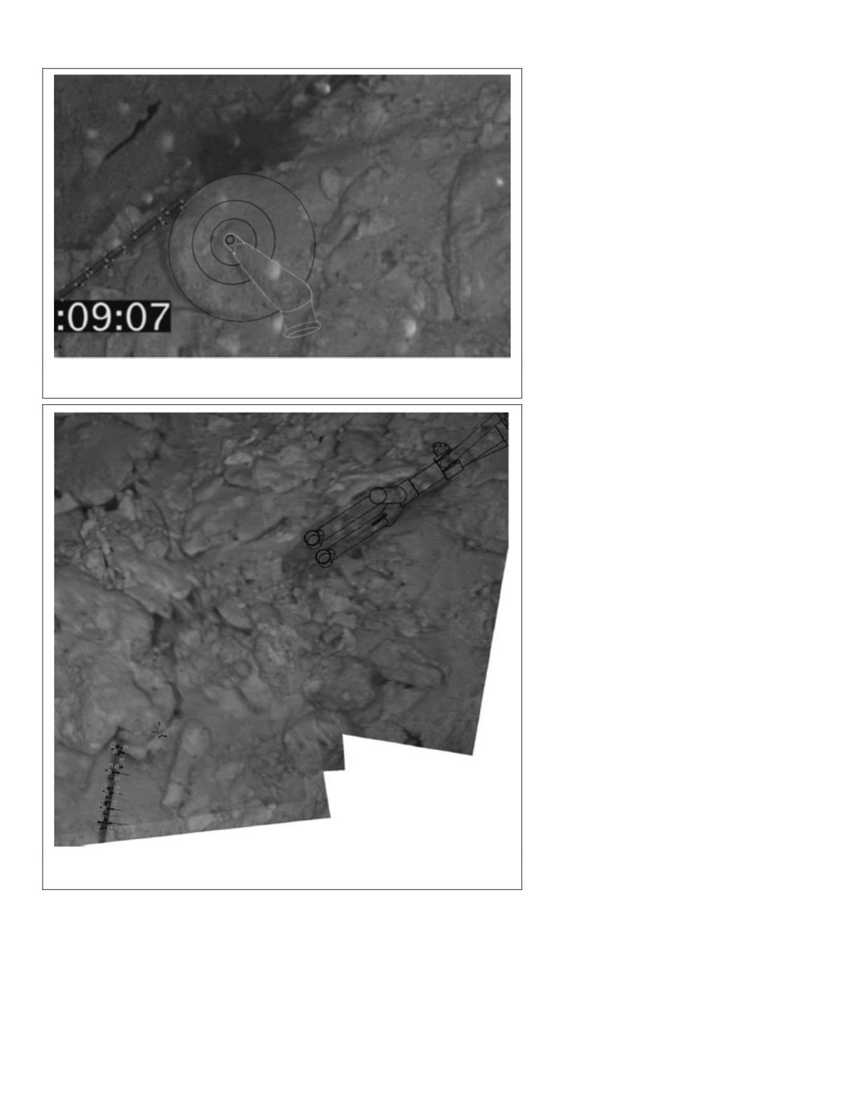
(Figure 9). Using the
CAD
front landing
gear as a size reference, the rope was again
measured at five locations and was identi-
fied to have a diameter of 18.0 mm, with a
standard deviation of 0.8 mm (Figure 10).
ROV Claw
An opportunity arose during analysis of
the video to retrospectively create a scale
marker based on a man-made object, even
though no markers were intentionally used
to shoot the video. An
ROV
articulating
claw was observed in the video grasping a
rope. The dimensions of the claw were ini-
tially unknown, but information about the
ROV
was discovered after reviewing data
embedded in the RAW video. The video
data contained information that allowed
us to identify the model of submersible
used. The articulating claw seen in the
video was then identified based on discus-
sions with the submersible manufacturer.
A reference claw was then acquired from
the
ROV
manufacturer and analyzed, mea-
sured, and photographed.
The claw was then compared against
ropes of differing diameters (Figure 11). Of
the three diameters tested, the 15.9 mm di-
ameter rope most closely matched a video
scene where the claw grabbed the rope. A
second estimate of the rope diameter was
made using video footage of the claw. Us-
ing known dimensions of the claw, scale
references were applied to a still image
from the
ROV
video of the claw (Figure 12).
The camera’s principal axis is approxi-
mately perpendicular to the rope. The rope,
together with the camera’s principal axis,
creates a depth plane. Dimensions of cross-
sections of objects cut by this plane are
photogrammetrically comparable. Note that
dimensions across different depth planes
cannot be compared because the magnifica-
tion factor is unknown. The cross-section
dimensions of the lightening holes of the
ROV
claw at the depth plane of the rope
was measured to be approximately 15.24
mm, which provides scale to the image. The estimated rope
diameter was then calculated to be approximately 15.24 mm.
Method Verification
A
rear landing gear from was acquired from an extant Lock-
heed Electra Model 10E, construction number 1042. This
exemplar landing gear was posed and photographed from a
similar perspective to the unidentified object in Figure 9. The
Figure 9. Using the CAD rear landing gear as a size reference, the rope was identified to
have a diameter of 15.5 ±0.3 mm.
Figure 10. Using the CAD front landing gear as a size reference, the rope was identified
to have a diameter of 18.0 ±0.8 mm.
228
March 2016
PHOTOGRAMMETRIC ENGINEERING & REMOTE SENSING


