modern tire on this exemplar landing gear is different from
the historical tire on Amelia Earhart’s Lockheed Electra, so for
this part of the analysis, a
CAD
model was created based on
measurements taken from the exemplar tire, which measured
approximately 343×178 mm. A 15.9 mm diameter manila
rope was laid next to the rear landing gear for comparison.
For a qualitative assessment, the image of the exemplar
rear landing gear with the 15.9 mm diameter rope was scaled
and superimposed on a single perspective digital mosaic cre-
ated from the
ROV
video (Figure 13) for a visual comparison.
This was performed by scaling the tire from the real landing
gear to the size of the purported tire seen in the
ROV
video.
For a quantitative assessment, dimensional analysis using
a photograph of the exemplar rear landing gear and a
CAD
model of the exemplar gear was performed in the same man-
ner within SolidWorks as was performed for the
ROV
images.
The rope was measured at five locations within SolidWorks
and was identified as having a diameter of 15.5 mm, with a
standard deviation of 0.5 mm (Figure 14). The known rope
diameter, as measured with digital calipers, was 15.9 mm.
Results
Using the
CAD
model of the front landing gear superimposed
on the stitched image from the
ROV
video, the diameter of the
rope was measured at five locations, having an average diam-
eter of 18.0 mm with a standard deviation of 0.8 mm. Similar-
ly, using the
CAD
model of the rear landing gear superimposed
on the stitched image, the diameter of the rope was measured
at five locations, having an average diameter of 15.5 mm with
a standard deviation of 0.3 mm. Dimensional analysis of the
video which contained the
ROV
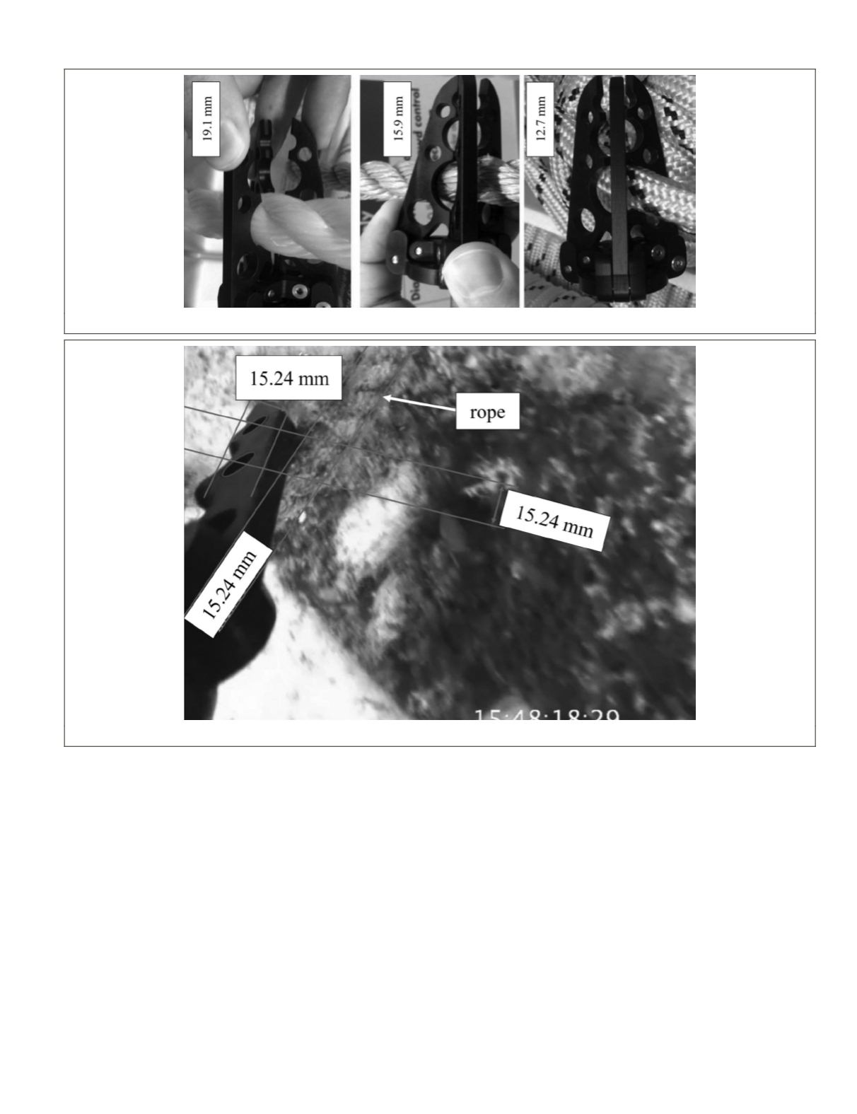
’s claw identified the rope
diameter as approximately 15.24 mm.
Discussion
While scaled orthogonal projections yield true dimensions
along the plane of the projection, it is not always feasible to
generate an orthogonal image, and a perspective image must
be used. In this case study, the camera is specified to have a
focal length between 5.1 mm and 51.0 mm, although the focal
length at the time of capture is unknown, but constant. The
Figure 11. Varying rope diameters (from left to right, 19.1 mm, 15.9 mm, 12.7 mm) were compared against the articulating claw.
Figure 12. Image-based rope dimensional analysis from the video.
PHOTOGRAMMETRIC ENGINEERING & REMOTE SENSING
March 2016
229


