processes are iteratively continued until a stable solu-
tion of the principal point is received.
2. The proposed approach can obtain more satisfactory re-
sults compared with the method without ellipses. This
is mainly because the principal point and the principal
distance in the second step of the proposed approach
are optimized by multiple pairs of orthogonal vanish-
ing points which are calculated through the ellipse and
vanishing line. Therefore, the proposed method can
obtain more satisfactory and stable results in the differ-
ent levels of
k
1
.
3. When the level of
k
1
= ±1.00
E
-09 (
pixel
-2
) is very weak,
all these methods can obtain appropriate accuracy. But
the proposed method significantly outperforms the meth-
od presented by van den Heuvel with the increase of
k
1
.
4. The re-projection errors through the three methods
also show that the proposed approach can obtain more
satisfactory results than the two other methods with
the increase of
k
1
.
Experiment 2 (Varying the Distortion Center)
In the second series of experiments, the distortion center was
varied while keeping the first radial distortion coefficient
fixed at a moderate level of distortion
k
1
= 1.00
E
-7(
pixels
-2
).
The levels of the distortion center (the principal point) were
set as (0,0), (10,10), (20,20), (30,30), (40,40), (50,50), (60,60),
(70,70), and (80,80) (pixels × pixels). In order to simplify the
presentation, the levels of distortion center are named as
r
d
=
0, 14.14, 28.28, 42.43, 56.57, 70.71, 84.85, 98.95, and 113.14
(
pixels
). The parameter
r
d
represents the distance between the
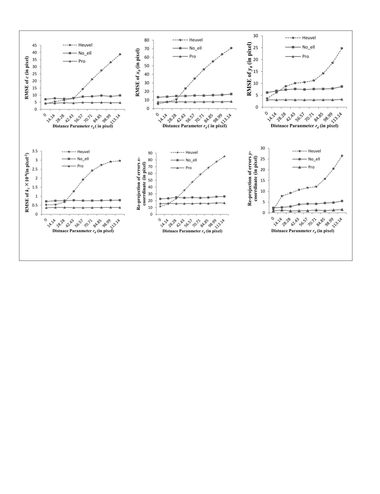
distortion center and the image center. The results of the three
methods (Heuvel, No_ell, and Pro) are presented in Figure 7a
through 7f).
From the results illustrated in Figure 7, the following con-
siderations can be outlined:
1. As the distance parameters of radial distortion in-
creases, the errors of the camera parameters
c
,
x
0
,
y
0
,
k
1
obtained by the method presented by van den Heuvel
become nearly linear large. But the method without
ellipses and the proposed approach can get more stable
results in different levels of
the distortion center, as
result of the loop optimization. Likewise, due to use of
the circle/ellipse, the proposed approach gets most sat-
isfactory results than the other two methods. Therefore,
the different levels of the distortion center
almost do
not affect the proposed approach.
2. The re-projection errors through the two methods also
illustrates that the proposed approach significantly out-
performs the other two methods with varying distor-
tion center.
Experiments 3 (Varying Circle Size and Location)
In the third series of experiments, the influence of the circle
size and location on the results was considered, respectively.
In all the experiments, the first radial distortion coefficient
was fixed at
k
1
= 1.00
E
-7 (
pixels
-2
), and the distortion center
was fixed at (
x
0
,
y
0
) = (30, 30) (pixels × pixels). In the first
experiment, the circle radius was varied while keeping the
circle center fixed at the center of the plane where the circle
is. The levels of circle radius were set as 10, 20, 40, 60, 80,
100, 120, 140,160, 180, 200, 220 mm. The results are pre-
sented in Figure 8a and 8b. In the second experiment, the
(a)
(b)
(c)
(d)
(e)
(f)
Figure 7. Results of experiment 2 using simulated data: (a) through (d) respectively represent the results of camera parameters
c
,
x
0
,
y
0
,
k
1
with varying the distortion center; and (e) and (f) represent the RMSE of re-projection errors of all the 3D points with varying distortion center.
330
May 2016
PHOTOGRAMMETRIC ENGINEERING & REMOTE SENSING


