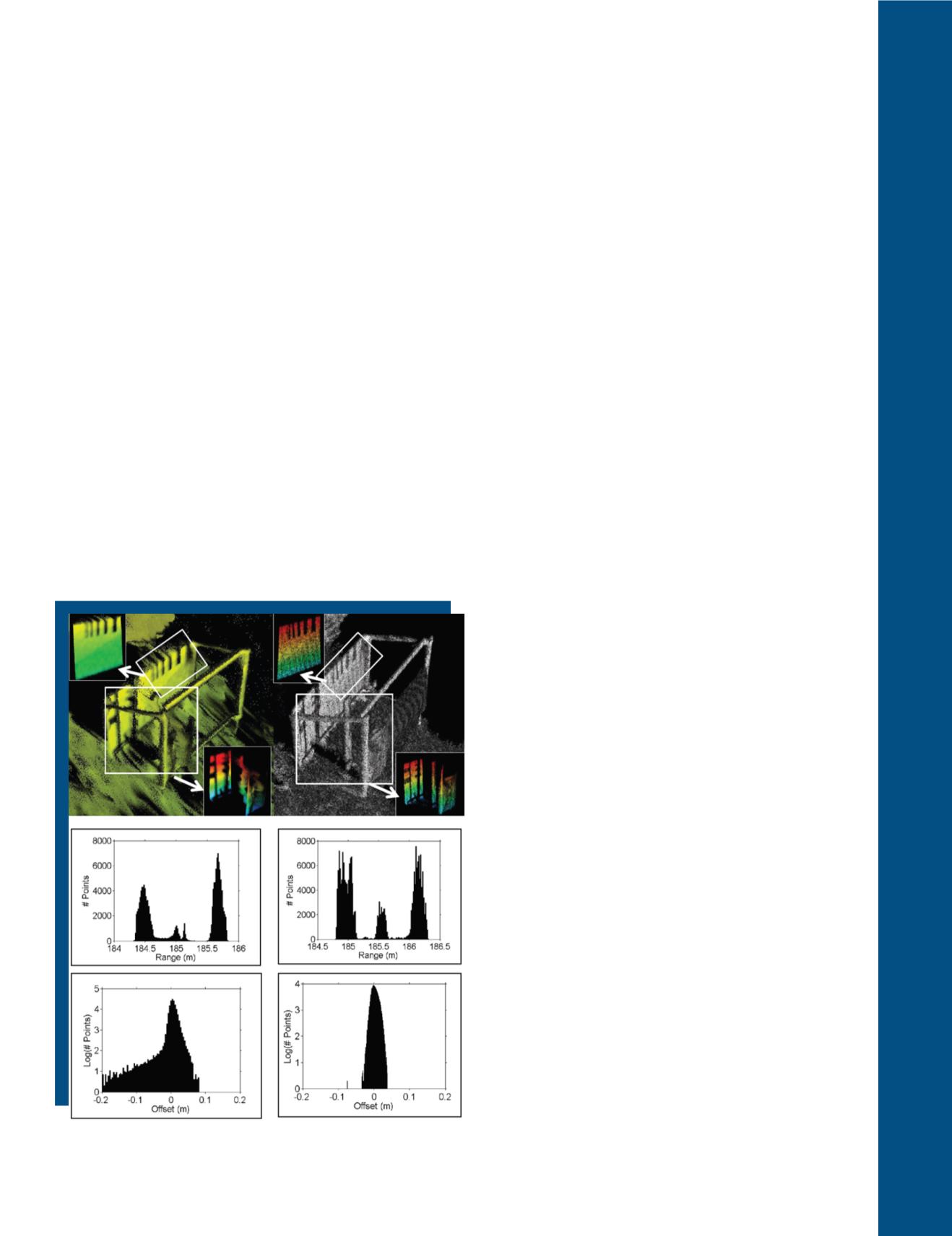
technologies. These are illustrated as insets in the point
cloud images with the VZ400 data to the left and the
FMCW HRS-3D data to the right. The first histogram
set presents data from the first area that includes the
double-layered mesh, vertical support, and backboard of
Box 2 for the VZ-400 (middle left) and HRS-3D (middle
right). The VZ-400 histogram shows 4 distinct peaks with
the first peak at 184.5 m due to the double-layered mesh
surface. This material is not resolved by the VZ-400 as
two separate surfaces. The second and third peaks are
located at 185 m and 185.15 m, respectively. The double
peaks here are due to a range ‘pulling’ effect induced by
the mesh. This effect is due (in part) to: 1) the inability
of the linear mode system to resolve objects outside of its
pulse bandwidth; and 2) the physical movement of the
mesh material during the scan event as a result of wind.
The upper portion of the wooden vertical support (box
inset) has a clear line-of-sight to the scanner while the
lower portion has the double layer mesh intervening the
scanner’s line-of-sight to the vertical support. The back-
board return is located at approximately 185.7 m. There
is also a considerable ”filling-in” of returns between the
mesh and vertical support in the VZ-400 data as can be
seen between 184.5 and 185 m. The HRS-3D data shows
three distinct range return peaks around 185 m. Two of
these are due to the double-layered mesh (a separation
of only a few cm) while the third peak is due to the hori-
zontal frame at the bottom of Box 2. The central vertical
support at 185.55 m and the backboard at 186.2 m are
both clearly defined in these range returns. There are
a few spurious returns in the HRS-3D data located at
185.3 m range. The fill-in observed between the vertical
support and the backboard at ranges of 185.7 m to 186
m was due to low-lying vegetation.
Analysis of the second area from Box 2 is comprised of the
backboard containing the vertical black resolution test
lines as can be seen in Figure 6 top left and right insets.
For each of the sub-set point clouds, a vertical plane was
calculated to act as the geometrical representation of the
backboard. The distance between the backboard plane
and each point was then calculated. This distance is the
offset between the 3-D data point and the vertical plane.
Logarithm histograms of the distance offsets are shown
in Figure 6 for the VZ-400 (bottom left) and HRS-3D (bot-
tom right). Negative and positive distance offset values
represent points behind and in front of the backboard
from the scanners’ viewpoints, respectively. The VZ- 400
histogram shows a distinct negative offset shoulder. This
is due to range ambiguities between the top of the
back-
board and a tree limb located approximately 0.5 m behind
Box 2. The positive distance offset shoulder shows that
the VZ-400 registered returns out to 8 cm in front of
the backboard. Meanwhile, the HRS-3D histogram
shows that there is no such range ambiguity between
the backboard and the tree behind Box 2. Additional-
ly, the distance offsets are confined to ± 5 cm from the
backboard plane (Massaro et al., 2014).
Finally, several long-range scans were acquired to ana-
lyze the performance near the limit of detection for each
system. Scans from the VZ-400 (Figure 7A) and HRS-
3D (Figure 7B) were acquired of a house and its sur-
roundings. The house was located approximately 500
meters from the scanner. As is apparent from Figures
7A and 7B, both systems easily captured the house and
the surrounding terrain and vegetation. However, the
high range resolution provided by the HRS-3D is able
to render the detail in the roofing material and textur-
ing as can be seen in the bottom images of Figures 7A
and 7B. A slightly subtler observation is the absence of
points from the VZ-400 scan (Figure 7A) on the lawn in
front of the house and in the vegetation to either side of
the house. It is expected that this is
due to the detection
range limit of the VZ-400, especially when considering
the oblique viewing geometry of the lawn from the
scanners. The HRS-3D is able to acquire points from
a large swath of the lawn and is also able to render far
more detail within the vegetation.
Figure 6. Point clouds and histogram analysis for Box 2, with VZ-400
data presented left and FMCW HRS-3D data presented right.
PHOTOGRAMMETRIC ENGINEERING & REMOTE SENSING
November 2017
725


