Introduction
First demonstrated in the 1960’s, Light Detection and
Ranging, or LiDAR has enjoyed rapid development in
the last 25 years or so following the technological revo-
lution in laser optics, computers and ultra-fast and ac-
curate timing mechanisms (Vosselman and Maas 2010;
Shan and Toth, 2008). Only recently have these tech-
nologies aligned and advanced enough to support large-
scale topographic measurement within a reasonable
amount of time. In remote sensing, surveying and map-
ping,
pulsed
LiDAR systems have dominated and made
the greatest strides in the past 10 to 15 years. Pulsed or
linear mode LiDAR involves accurate measurement of
the Time-of-Flight of an intense pulse of laser light as
it is emitted, then reflected and subsequently returned
to the detector. The pulse echo represents the distance
to and from a reflected surface as compared to the time
elapsed between emission of photons from a laser
and their return (Amman et al. 2001).
Terrestrial LiDAR instruments are now able
to collect millions of accurately geo-referenced
points within several seconds, with increased ac-
curacy in digital time counters (down to the pi-
cosecond) and ever-increasing range resolutions
constantly being achieved. While the pulsed Li-
DAR technology is currently the most mature
light measurement approach, frequency-modu-
lated continuous wave (FMCW) LAser Detection
And Ranging (LADAR) is rapidly gaining ground
due to several key benefits, including:
•
Doppler imaging and motion detection;
•
lower power to achieve greater range mea-
surement or, conversely the ability to detect
objects at a greater range than linear mode
LiDAR possessing the same power; and finally
•
greater spatial detail and resolution at range
(Massaro et al. 2014).
The abbreviation ’LADAR’ is used here in that FMCW
technology is best described as emulating a modern op-
tical radar in its functionality. FMCW LADAR has also
been referred to as “phase comparison” LiDAR and has
its roots in metrology where coherent techniques allow
for bandwidths capable of resolving extremely small
ranges of micron-level (depending on the frequencies
used) at nanometer precision (Roos et al. 2009; Mateo
and Barber 2015). Unlike linear mode scanning, FMCW
technology involves a continuously emitted laser beam
on which a modulation signal is superimposed to pro-
vide the range measurement. A local oscillator is creat-
ed as a timing reference whereby some of the transmit-
ted light is split and used as a reference field to mix with
the reflected light. (Amann et al. 2001).
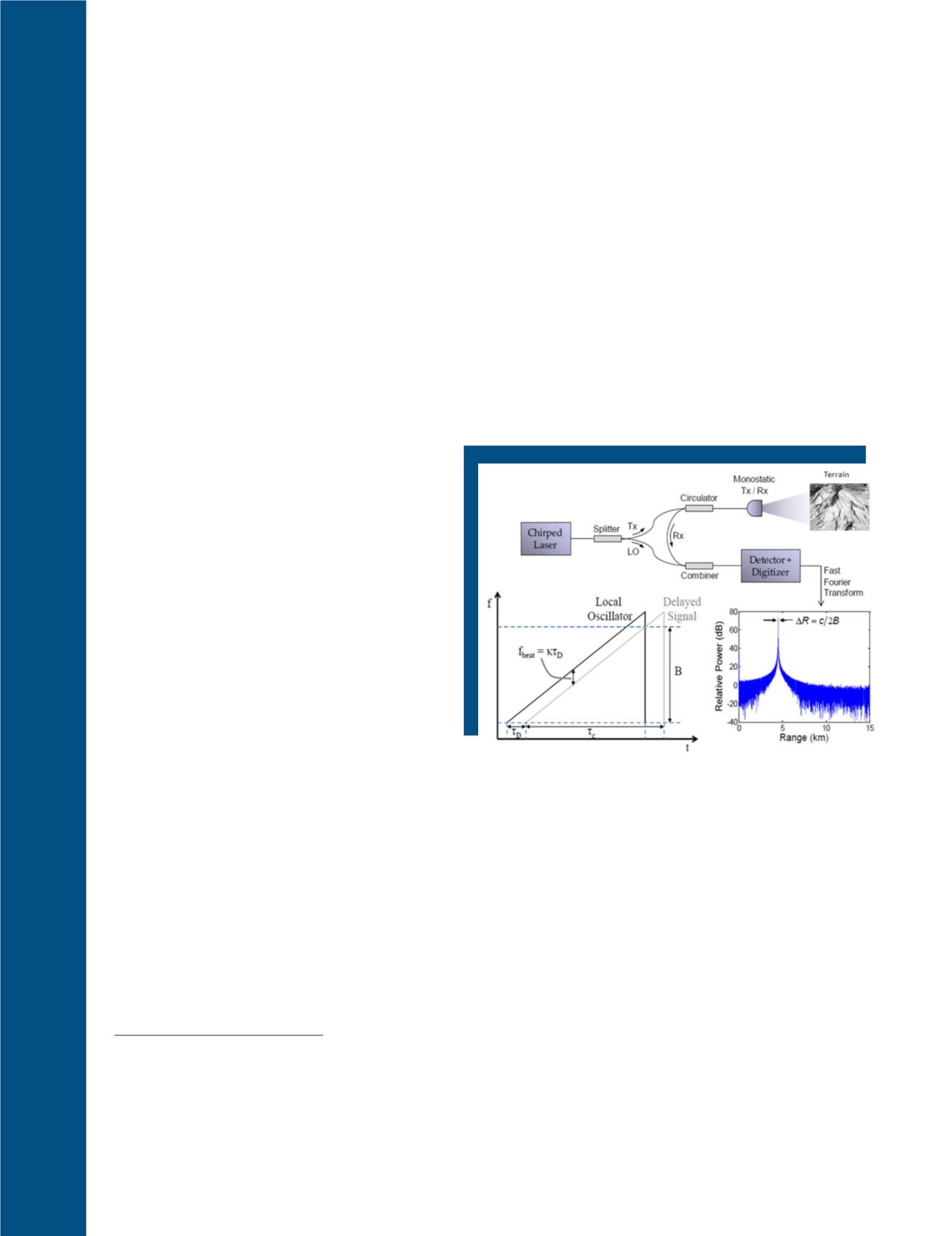
In FMCW scanning, as in linear mode, a reflective
target is illuminated, but not by using a pulsed laser
source. Instead, the FMCW system continuously illumi-
nates the target. Upon its return to the detector, the re-
flected measurement signal is demodulated, resulting in
the separation of the measurement and carrier signals
(Figure 1). Once separated, the reflected measurement
signal is compared to the original timing reference to
derive the difference in phase angle and determine the
beat note frequency, (
κτ
D
).
However, this only partial-
ly resolves the total slant range (
R
), known as the am-
biguity resolution issue. To complete the derivation of
R
, the FMCW system ‘chirps’ the laser to change the
frequency in rapid succession to acquire multiple phase
angles necessary for resolution. For a set of frequencies,
it is typically the rule that the lower frequencies in the
FMCW are associated with the longest wavelength and
are used to determine the range (
R
). Range resolution
in FMCW is determined by the highest frequency and
hence the shortest wavelength (Brown 2011; Shan and
Toth 2009). In typical linear mode LiDAR where Gauss-
ian-shaped laser pulses are emitted, the range resolu-
tion is limited by the width of the emitted laser pulse.
Whereas FMCW is limited in range resolution only by
the chirped bandwidth of the emitted beam (Reibel et
al., 2010).
Figure 1. FMCW schematic (after Barber et al. 2010 and Reibel et
al. 2010) showing relevant signal relationships and range determi-
nation by frequency measurement.
722
November 2017
PHOTOGRAMMETRIC ENGINEERING & REMOTE SENSING
Photogrammetric Engineering & Remote Sensing
Vol. 83, No. 11, November 2017, pp. 721–727.
0099-1112/17/721-727
© 2017 American Society for Photogrammetry
and Remote Sensing
doi: 10.14358/PERS.83.10.721


