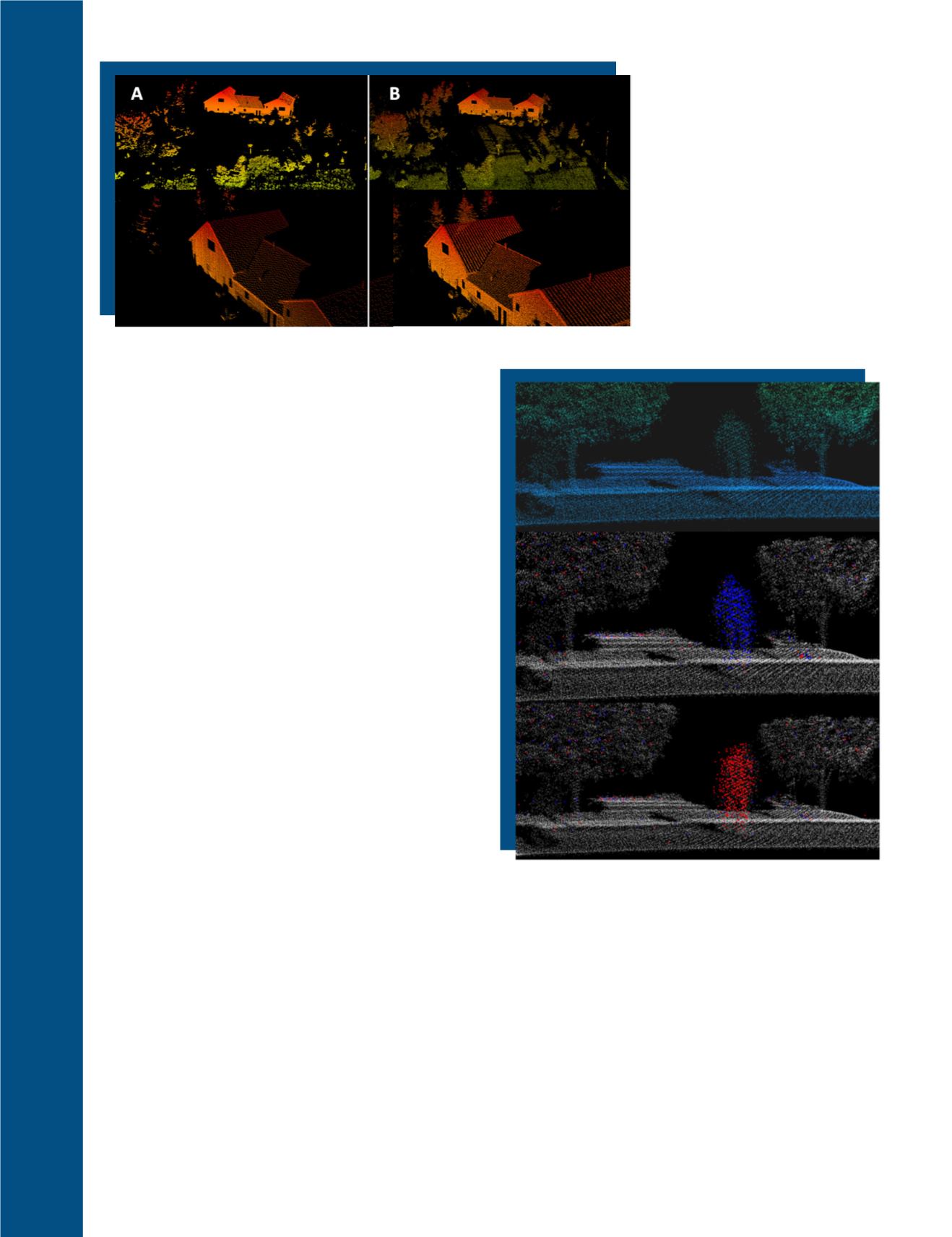
Figure 7A and 7B. Figure 7A. (Top)
VZ-400 scan of house and surround-
ings at a range of approximately
500 m. (Bottom) Zoomed-in view of
house. Figure 7B. (Top) HRS3D scan of
house and surroundings at a range
of approximately 500 m. (Bottom)
Zoomed-in view of house. Note the
clearly textured roof.
Doppler Imaging and Topographic Point Return
As described, one advantage of frequency domain laser
scanning is the ability to acquire Doppler information
about a target. This is done in almost the exact same
way that radar resolves range and velocity informa-
tion. A stationary reflecting object results in a tone at
a specific frequency related to the object’s range. How-
ever, if the reflecting object is moving with respect to
the receiving optics of the LADAR, the echo signal is
shifted by the Doppler effect to some frequency other
than what is expected for a stationary object at the same
range. The system measures only this Doppler-shifted
frequency. Depending on the movement direction and
the direction of the linear modulation this is either the
sum or the difference between the difference frequency
(as the carrier of the range information), and of the Dop-
pler-shift frequency (as a carrier of the velocity informa-
tion). There exists in this measurement an ambiguity
between range and velocity. To make an accurate range
measurement, the velocity information must be known,
and vice versa. The ambiguity is typically broken by the
use of sequential chirps moving in opposite directions
(Goodwin et al. 1989; Halmos et al. 1989). Comparing
the observed frequencies in the two opposing chirps re-
veals the direction and magnitude of the Doppler shift,
enabling the recovery of the correct range to the target
as well. If a reflecting object is moving with respect to
the receiving optics of the LADAR , then the echo
of
the
received signal will show a higher frequency when the
target
is approaching
and a lower frequency when the
target
is moving away
from the LADAR. The amount
of Doppler shift is directly proportional to the radial
speed of the target. Doppler imaging results when both
phenomena are recorded and presented, as in Figure 9.
In this point cloud, motion is shown as the subject is
stationary and then moves toward the LADAR (in blue)
and moves away from the LADAR (in red).
Figure 8. (
TOP
) Height-colored scene from FMCW LADAR.
Parked motorcycle on left, followed by tree, walking
person, and another tree on the far right. (
MIDDLE
) Dop-
pler-colored scene from FMCW LADAR. Parked motorcycle
on left, followed by tree, walking person, and another tree
on the far right. The points on the person are shaded blue
because the person is approaching the sensor. Most other
points are shaded white/grey because they are stationary.
(
BOTTOM
) Doppler-colored scene from FMCW LADAR.
Parked motorcycle on left, followed by tree, walking
person, and another tree on the far right. The points on
the person are shaded red because the person is walking
away from the sensor. Most other points are shaded white/
grey because they are stationary.
726
November 2017
PHOTOGRAMMETRIC ENGINEERING & REMOTE SENSING


