Geometric Reasoning
The usefulness of the approach is demonstrated utilizing a
polyhedral building model obtained from an airborne laser
scan. We derive the uncertainty of the planes corresponding
to the faces of the boundary representation, perform the geo-
metric reasoning, determine a set of independent constraints,
and eventually conduct an adjustment to enforce the inferred
constraints.
In the data analysis step, the points of the laser scan have
been classified into roof and non-roof points. The points
representing roof areas have been grouped by utilizing the
RANSAC-based shape detector (Schnabel
et al
., 2007) pro-
vided by the mesh processing software CloudCompare.
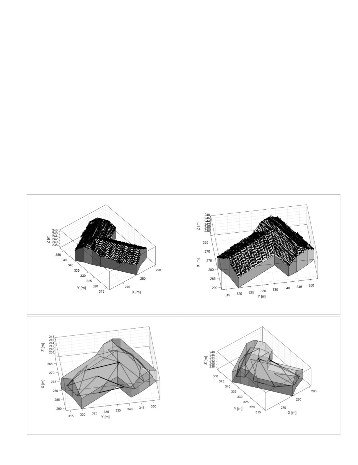
Figure 3 shows points captured by a RIEGL LMS-Q560
scanner representing the roof of a farmhouse and a corre-
sponding boundary representation. The reconstruction has
been carried out by initially performing a 2D triangulation
and computing alpha-shapes to determine the building’s out-
line. The triangles with points of different planar point groups
constitute the boundaries of the roof sections. By analyzing
the sequence of the border points, we obtained the interior
roof structure, i.e., ridge lines, step-edges, and roof valleys.
All traversed lines have been simplified by vertex decimation.
The solid has been closed by assuming vertical walls on top
of the irregularly shaped outline.
In Figure 3 also the result of an analysis from the point
cloud to a polyhedral boundary model is shown. In this paper
we do not assume the uncertainty of the resulting planar
patches to be known. However, we assume the standard de-
viations, except for a common factor, depend on their shape.
As a result, we obtain a generic representation of the build-
ing. Only for the non-observed building parts, i.e., the walls
and the floor, model assumptions are used. However,
the
result does not provide information about its uncertainty
.
After the determination of the planes’ uncertainties, we
derived the set of constraints with a significance level of
α
=
0.05. Very small or thin roof areas are usually very uncertain.
Therefore, it is likely that hypotheses involving these faces
are not rejected and wrong constraints will be inferred. Thus,
we suppress constraints with faces featuring areas smaller
than 16 m
2
.
Figure 4 shows the boundary representation of the build-
ing with the inferred constraints: 28 times orthogonality and 5
times identity have been detected. The numerous constraints
for the ground floor are not visualized for the sake of clarity.
A vertex of our boundary representation is defined by the
intersection of at least three planes defined by the building’s
faces. Thus, identical or almost identical planes will lead to
undetermined vertices. Therefore, we merge adjacent faces
which have been identified to lie in the same plane in a pre-
processing step. Figure 5 shows the result of this simplifica-
tion. After applying the hypothesis testing with the new faces,
a set of 20 orthogonality constraints remains.
Figure 3. Points of an airborne laser scan captured by a RIEGL LMS-Q560 scanner and the deduced boundary representation
in two views. The points represent the roof areas of a farmhouse.
Figure 4. Derived constraints for the initial boundary representation with 19 faces, depicted in two views. 28 times
orthogonality (—) and 5 times identity ( … ). The numerous constraints for the floor are not depicted for the sake of clarity.
PHOTOGRAMMETRIC ENGINEERING & REMOTE SENSING
June 2018
399


