where (
X,Y
) are the planimetric coordinates of a ground point;
f
represents the focal length; (
X
S
,Y
S
, Z
S
) are the coordinates of
a perspective center; and
r
11
,
r
12
, …,
r
33
are the nine elements
of a 3 × 3 rotation matrix. All the exterior orientation param-
eters used in Equation 2 are time-dependent and should be
interpolated from navigation data by the corresponding scan-
line coordinate (i.e., the
x
-coordinate of the L0 image).
Object-to-Image Projection
Ground points are first required to be projected to the focal
plane by the use of the collinearity equations.
x f
r X X r Y Y r Z Z
r X X r Y Y r Z
S
S
S
S
S
F
= −
−
(
)
+ −
(
)
+ −
(
)
−
(
)
+ −
(
)
+
11
12
13
31
32
33
−
(
)
= −
−
(
)
+ −
(
)
+ −
(
)
−
(
)
+ −
(
Z
y f
r X X r Y Y r Z Z
r X X r Y Y
S
S
S
S
S
S
F
21
22
23
31
32
)
+ −
(
)
r Z Z
S
33
(3)
Note that Equation 3 cannot be directly used in practice
because the corresponding exterior orientation parameters of
an arbitrary ground point are not explicitly known. Conse-
quently, a sophisticated scan-line search algorithm should be
first applied (see the next section for details), and the exterior
orientation parameters can then be interpolated from the
navigation data by the obtained scan-line coordinate.
The second step of the object-to-image projection is to
convert the focal-plane coordinates to L0 image coordinates.
The
x
-coordinate of the L0 image is already known from the
scan-line search, and the
y
-coordinate can be obtained by:
y y
y
y
y
y
n
y n
y n
y n
= +
−
−
+
F
cal
cal
cal
[ ]
[
]
[ ]
1
.
(4)
Note that Equation 4 only describes the interpolation be-
tween two adjacent integer pixels, i.e.,
n
and
n
+1, where
n
is
determined by comparing
y
F
against cal
y
[ ] in advance.
Criteria for Scan-line Search Algorithms
An important issue in developing a scan-line search algo-
rithm is to evaluate how accurate the current search result is.
Previous studies provided two feasible solutions: the focal-
coordinate-difference based criterion (the
Δ
x
F
criterion) (Zhao
and Li, 2006) and the point-plane-distance based criterion
(the
D
criterion) (Wang
et al
., 2009).
For a ground point (
X,Y, Z
) and a given scan-line coordi-
nate (i.e., the
x
-coordinate in the L0 image), its corresponding
focal-plane coordinates (
x
F
,y
F
) and the
y
-coordinate in the L0
image can be calculated using Equations 3 and 4, respectively,
while another set of focal-plane coordinates (
x
ˆ
F
,y
ˆ
F
), which are
correct, can be derived from Equation 1. If the input scan-line
coordinate is accurate, the difference (
Δ
x
F
,
Δ
y
F
) between the
two focal-plane coordinate sets, i.e., (
x
F
–
x
ˆ
F
,
y
F
–
y
ˆ
F
), should
be (0,0) because of the collinearity constraint. Given that the
discrepancy in the
y
F
component is always subject to that in
the
x
F
component, we can set the
Δ
x
F
criterion: the input scan-
line coordinate is correct only if
Δ
x
F
= 0 (Zhao and Li, 2006).
The scan-line search algorithm based on the
Δ
x
F
criterion
needs to repeatedly project a ground point to the focal plane
using different scan-line coordinates, and to verify whether
the collinearity constraint is satisfied. According to Wang
et
al
. (2009), these calculations are somewhat time-consuming
and can be approximately replaced by a simpler operation:
calculating the point-plane distance.
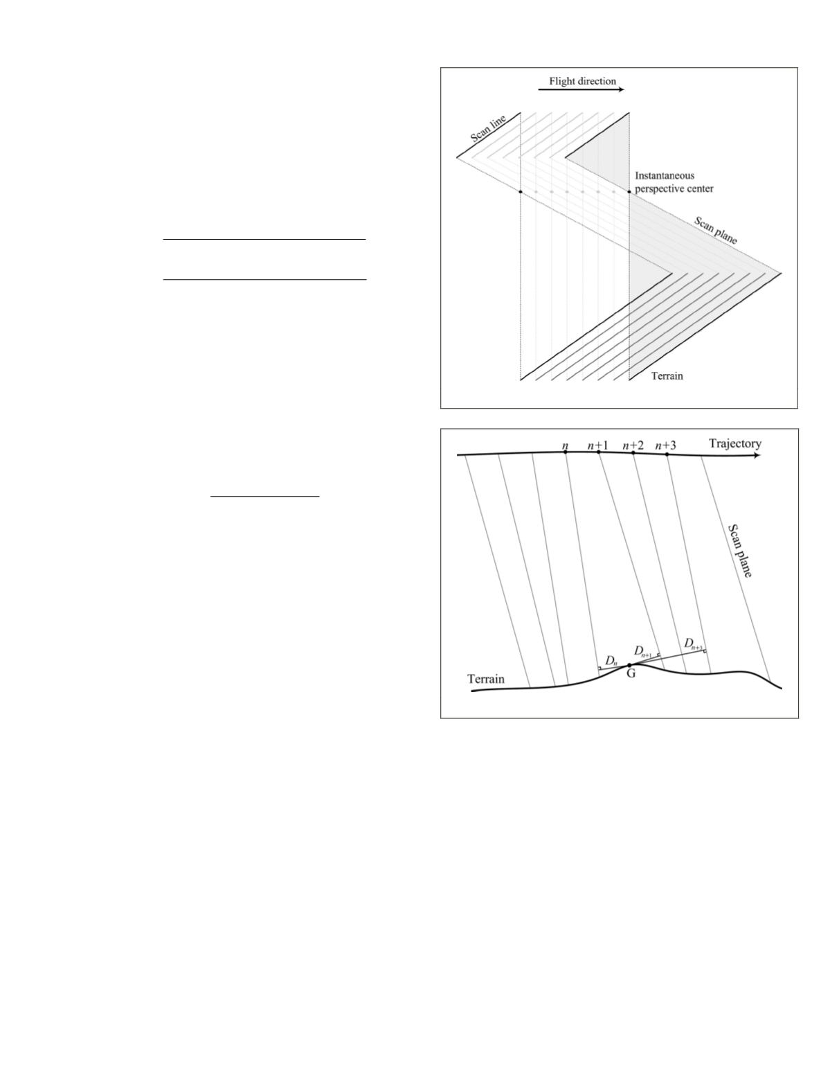
As schematically shown in Figure 4, assuming that the
CCD
detectors are ideally distributed along a straight line on the
focal plane, a scan plane can be formed by a scan line and its
corresponding instantaneous perspective center (Wang
et al
.,
2009). If the distance
D
from a ground point to a scan plane is
smaller, the corresponding scan-line coordinate is commonly
more accurate (see Figure 5), which is referred to as the
D
criterion. However, in practice, the
CCD
arrays are actually
curved on the focal plane (see Figure 2), and polylines should
therefore be used to approximate the curved
CCD
arrays. As a
result, the
D
criterion can only be applied to the coarse stage
of the scan-line search (Wang
et al
., 2009).
Method Description
The proposed scan-line search algorithm consists of four
steps, as follows.
1. Affine transformation
This step aims to provide a very coarse initial value for
the subsequent iterative search at a fairly low computa-
tional cost. Its accuracy is typically within the range of
50 to 500 pixels, depending largely on the orientation
variations of the platform. A preprocessing procedure
is needed to calculate the affine transformation pa-
rameters, as follows: several (at least three) points at
Figure 4. Formation of scan planes.
Figure 5. The distance
D
from a ground point to a scan plane.
PHOTOGRAMMETRIC ENGINEERING & REMOTE SENSING
July 2015
567


