may not be a requirement for urban watershed delineation for
a location with similar terrain and land use.
Actual boundary differences were more pronounced and
may have more influence on the water flow in an urban area.
The lidar-delineated watershed appeared to provide a better
account of impervious surfaces than did the coarser resolu-
tion
USGS
-derived watershed model. The lidar resolution, at
only one-meter
2
, was based on final returns of the lidar for the
surface elevation. However, neither delineation accounted for
additions or subtractions from the watershed resulting from
stormwater network inlets (curbside drains and manholes),
pipes, and retention facilities. After subtracting isolated net-
works from the watershed, and adding and subtracting the land
area with redirected flow because of the stormwater network
system, the area decreased by almost 17 percent. We further
note that additions and subtractions to the area of the lidar-de-
rived watershed caused by mis-definition of watershed bound-
aries not only alters the size of catchment, but also, by adding
and subtracting different land uses, can alter the hydrologic
character of the watershed, further misrepresenting its nature.
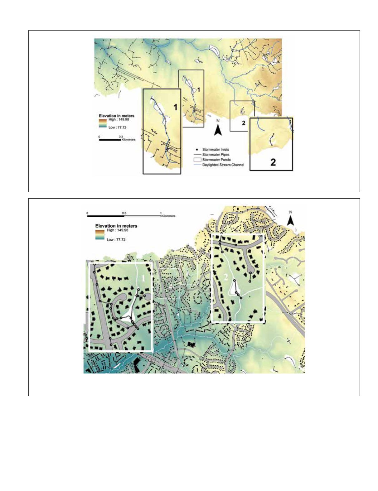
Plate 1. Examples of areas disconnected from the stream channel (blue lines). In Box 1, retention ponds (white) are connected to each
other by stormwater pipes (black lines) and inlets (black dots). In Box 2 stormwater inlets and pipes flow into a single retention pond.
Plate 2. Box 1 shows a stream channel (white lines) and stormwater pipes (black lines) directing water flow into a stormwater retention
pond (white polygon) and away from the main stream channel. Box 2 shows an area of a stormwater detention pond as the stormwater
pipes actually join disconnected stream channels to the main stream channel.
PHOTOGRAMMETRIC ENGINEERING & REMOTE SENSING
May 2015
371


