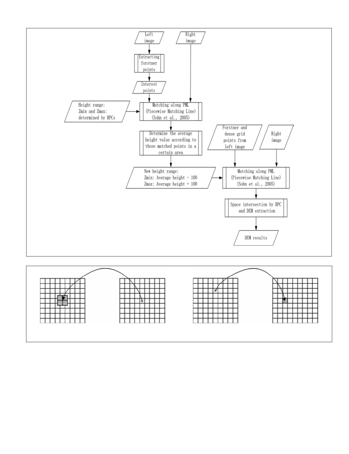
Figure 1. Flowchart of the proposed image matching algorithm.
(a)
(b)
Figure 2. Transformations of a pixel: (a) indirect, and (b) direct (Novak, 1992).
coordinates into the result, and places the gray value to the
nearest integer pixel (Figure 2b) (Novak, 1992).
Our method is similar to the abovementioned indirect
method. After determining the bounds used to save the final
results, the method divides the coverage of the bounds into
blocks according to spatial domain. Thus, a block is a certain
area covered by output bounds. To generate the final results
for each block, the idea of indirect method is used. Our
method begins each time taking a block instead of a pixel,
determines the region in the original image for this block
by a recursive manner, reads the data in the region, carries
out a sequence of steps, and writes the final results to the
block. This method has two improvements above the original
indirect method (Novak, 1992). It can process one block at a
time, and multiple steps can be incorporated into the indirect
procedure. Therefore, our method is not limited to geometric
correction. It can be used in many other algorithms, e.g., im-
age fusion and mosaic. Furthermore, the processing tasks of
multiple blocks can be distributed to multiple
CPU
cores with
the help of parallel computing techniques.
Block Partition in Output Bounds Used to Save Final Results
The coverage in output bounds, which is related to either an
image or another form (e.g., 3
D
points used for
DEM
extraction),
is partitioned into blocks. The final results of the algorithm
are generated after certain processing steps, and written into
PHOTOGRAMMETRIC ENGINEERING & REMOTE SENSING
May 2015
375


