176
April 2018
PHOTOGRAMMETRIC ENGINEERING & REMOTE SENSING
QC
of
L
idar
data
for
N
ational
L
idar
P
rojects
such
as
3DEP
Introduction
National projects including the 3D Elevation Program (3DEP)
are envisaged to support national and pan-regional scientific and
engineering goals. Many of the lidar acquisition projects have
scientific goals that are regional or sub-regional in scope. Their
geometrical quality assessments are also limited in their spatial
extent. Lidar data for scientific projects; such as, river systems
analysis, carbon sink assessments, interstate road networks,
watersheds, etc.; require data assessments that are similar in
scope, i.e. across projects. In practice, individual projects are
executed by USGS with other federal and local partners in a
more ad-hoc (spatially) manner.
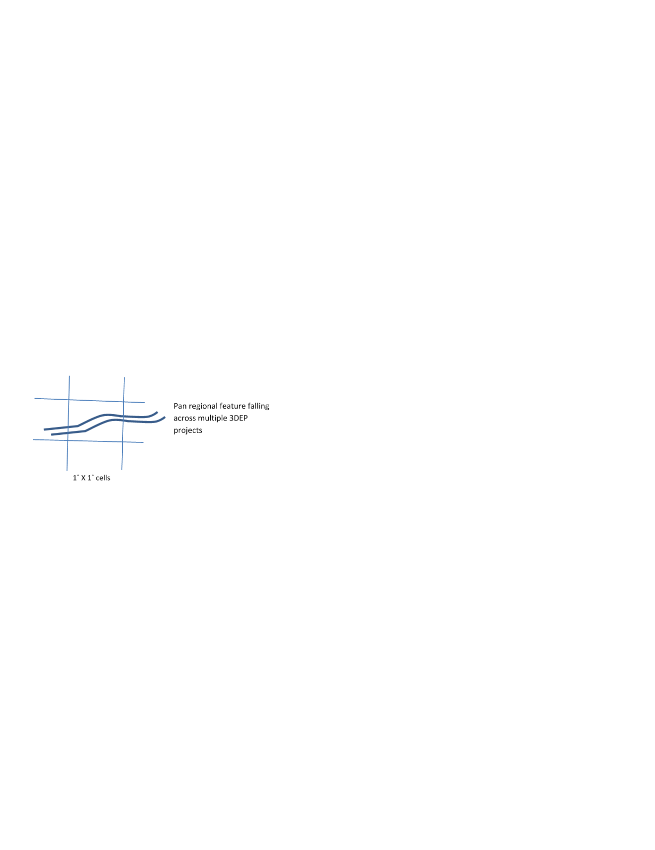
Many features; such as streams, roads, forests, etc., will span
multiple collections or projects. It is important to the scien-
tific community that these features are represented in a con-
sistent manner by the lidar data, even though the data may
be acquired by different vendors, using different sensors, and
at different times. The consistency between adjacent datasets
must be quantified and documented in the metadata.
Figure 2 Illustration of pan regional features of scientific
importance that require quantification of inter project
geometric alignments
Recommendations for Further Research
The WG recommends that government, academia and the
industry stakeholders research and develop methods for inter
project lidar data consistency. The specific questions that are
required to be answered include
•
How should inter project lidar data consistency be
mathematically defined?
•
How should the data consistency metrics be measured?
•
How should data acquisition be specified to ensure con-
sistency of features across spatial extents of different
projects?
•
Are there new technologies that can assist in enhancing
inter project lidar data quality?
QA
of
L
idar
data
using
S
ensor
M
odel
based
G
eometric
P
rocessing
M
ethods
Introduction
Geometric processing of raw data (GNSS, IMU, range, etc.)
to (X, Y and Z) point cloud uses parameters derived from
laboratory and self-calibration methods. The geometric process
often involves adjusting boresight and other parameters using
overlapping data and in conjunction with ground control points,
such that the resulting point cloud are internally consistent
and externally match the GCPs. The traditional procedure is a
manual adjustment process based on the operator’s expertise to
minimize error. However, the geometric processing parameters
are often correlated and it is easy to misinterpret the source of
errors. These procedures also implicitly assume that the other
geometric correction parameters hold their previously computed
values, which may not be the case. The results depend on
individual skill, experience of the operator, and are exhausting,
time-consuming and expensive. Traditional methods also have
the following drawbacks:
•
They do not allow estimation of error in the generated
data.
•
Data sets generated by different users cannot be easily
compared to each other.
•
The processes cannot be traced to an accepted standard;
i.e., the calibration is not conducted using a measure of
higher accuracy.
It is recommended that manufacturer provided automated
geometric processes be followed to the extent possible.
Rigorous Geometric Processing Methods
Rigorousgeometricprocessingmethodsarebasedondetermining
parameters that describe the sensor model completely (including
the provision of expected magnitudes of error). The parameters
include boresight parameters. Since many parameters
associated with a complete sensor model are proprietary,
software to perform rigorous geometric processing should be
provided by the instrument manufacturer. Alternately, sensor
manufacturers are encouraged to make their sensor models
open. Conceptually, the rigorous geometric process relies on
minimizing discrepancies between tie features using redundant
observations (data). These tie features must be features that
can be reliably extracted from point cloud data. Possibly the
easiest feature that can be reliably extracted from a point cloud
are planes. Breaklines can be treated as the intersection of two
planes, and points can be treated as intersection of at least
three planes. Most manufacturer provided rigorous geometric
processes have focused on extracting (sloping) planar features
(e.g. roof planes, etc.) from the overlapping portions of point
cloud, including those obtained from flying opposite directions,
cross-strips and from different altitudes. Each point lying on
the planar feature forms an observation equation (using the


