between adjacent
DEM
s does not blur the recorded topography
because of the consistent
DEM
quality and precise alignment.
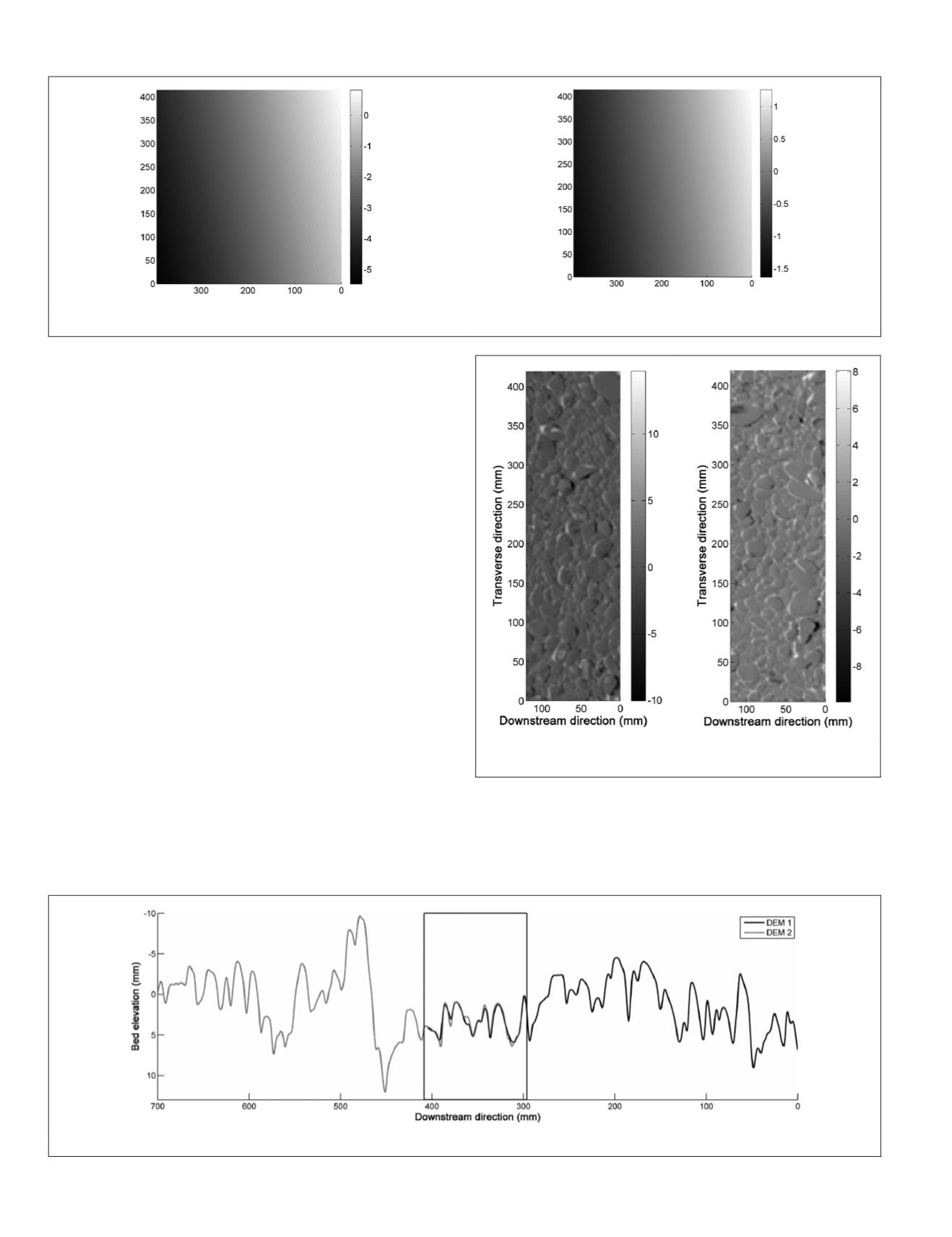
Co-registration prior to merging is essential. If not applied,
vertical shifts at the intersection between individual
DEM
s
can cause elevation disparities of up to 1 mm, and changes in
slope of up to 1.6 percent, as observed over the length of one
DEM
(Figure 6)
.
As merging is performed to capture information that
cannot be obtained by a single measurement, it is often
not feasible to have a suitable ground truth to evaluate the
merging success. For our stereo-photogrammetric applica-
tion, the accuracy and precision of an individual
DEM
was
evaluated previously, by measuring a 3
D
-printed ground truth
resembling a water-worked gravel bed (Bertin
et al
., 2014).
In the latter study, comparison of measured and “truth” data
resulted in a distribution of
DEM
errors characterized by a
statistical accuracy and precision of 0
·
43 mm (
MUE
) and 0
·
62
mm (
SDE
), respectively
.
The co-registration of individual
DEM
s can be assessed
without a ground truth. Figure 7 shows the two residual maps
after co-registration of
DEM
-1 and
DEM
-2, and
DEM
-2 and
DEM
-
3, respectively. Both residual maps are characterized by a zero
mean error (
ME
) and no blur, suggesting the horizontal regis-
tration precision of 1 mm (i.e., the
DEM
grid size) was suitable
for effective merging. Furthermore, no significant trend is
observed after co-registration, which concludes that any
DEM
misalignment prior to merging was correctly removed during
co-registration. We also recommend manual checking of the
combined longitudinal elevation profile (Figure 8), which can
be used as indication of accurate 3
D
co-registration between
individual
DEM
s
.
As comparison, the non-merged
DEM
, obtained using a
single stereo pair, is presented in Figure 9. The effect of
increased theoretical depth resolution (from 0.32 mm to 1.15
mm) and pixel size (from 0.14 mm to 0·26 mm), caused by a
larger camera-to-object distance (from 581 mm to 1,098 mm)
during image acquisition, is clearly visible. The non-merged
DEM
(Figure 9) loses sharpness and lacks detailed information
Figure 6. Trends in mm removed during vertical registration of overlapping DEMs. A linear surface is fitted to the residual maps (118 × 415
mm) using the least-squares method, which is then interpolated over the size of the DEM (395 × 415 mm). The sampling distance is 1 mm.
Figure 8. Longitudinal elevation profile, showing the area of overlap between DEM-1 and DEM-2, after co-registration.
Figure 7. Residual maps, i.e., elevation difference in mm between
adjacent DEMs after co-registration. The sampling distance is 1 mm.
36
January 2016
PHOTOGRAMMETRIC ENGINEERING & REMOTE SENSING


