water-work, particles of less than 5 mm in size were scarcely
represented on the gravel-bed surface
.
Two Nikon D5100 cameras in stereo, with 16.2 Mpixel
complementary metal oxide semiconductor (CMOS) sensors
(4,928 × 3,264 pixels) and Nikkor 20 mm fixed-focus lenses,
were used for the image acquisition of the dry gravel bed. The
setup was installed on a carriage, which can move along the
hydraulic flume and allowed for continuous acquisition of
overlapping stereo-pair sequences. To minimize the presence
of occlusions (also known as “dead ground”), a recurrent
problem on rough surfaces (Bertin
et al
., 2014; Chandler
et al
.,
2002; Chandler
et al.
, 2001), and simplify image rectification,
a standard vertical stereo-photogrammetric configuration was
used: optical axes parallel to each other and perpendicular
to the baseline. Even lighting of the test section was ensured
(Bertin
et al
., 2014)
.
Data processing was performed on an Alienware laptop with
Intel core CPU @ 2.20
GHz
, 8
GB
memory and MATLAB
®
2013b.
General DEM Collection Workflow
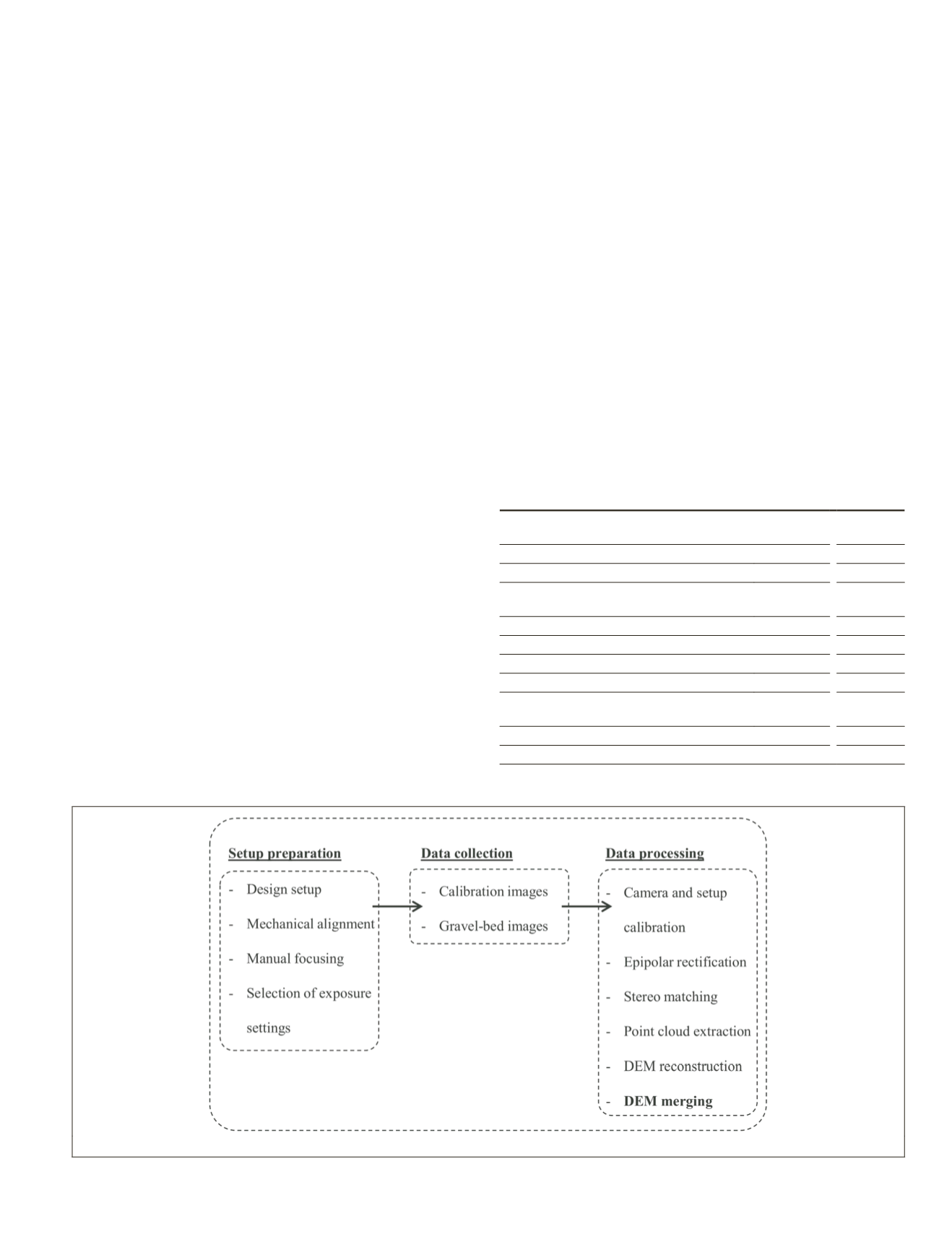
Figure 1 summarizes the general workflow developed and
evaluated in Bertin
et al
. (2014 and 2015) and used in this
study to reconstruct a 2.5
D DEM
from a stereo pair. The region
of interest is restricted by the
CFoV
formed by the two images.
Before presenting our new integrated
DEM
merging strategy,
we briefly summarize the main steps of our previous general
DEM
collection workflow, to allow for a comparison later on
.
The design of the setup is the first step of the workflow.
The aim is to find the minimum camera-to-object distance
that is needed to ensure the
CFoV
covers the region of interest
(Equations 1 and 2). The measurement resolution is depen-
dent on the region of interest and the cameras’ sensor size
(Equations 3 and 4). To measure a gravel bed (950 × 400 mm)
with one
DEM
(i.e., without merging) and a 5 percent margin
all around, the cameras were installed at a vertical distance
of 1,100 mm above the section. A baseline of 250 mm was
used, based on experimental heuristics. This results in a pixel
size and a theoretical depth resolution, at the distance of the
gravel bed, of 0·26 mm and 1.15 mm, respectively (Table 1)
.
After careful preparation of the setup, several stereo pho-
tographs of a flat checkerboard, necessary for accurate camera
calibration and pose determination, and one stereo pair of
the gravel bed, were recorded. The cameras were operated in
manual mode, using a combination of f/8 aperture,
ISO
200
and 1/20 s shutter speed. Data processing consisted in (a)
determining the camera calibration (e.g., principal distance,
principal point, and five-coefficient lens distortion) and pose
(3
D
rotation and translation between the two camera) param-
eters using the calibration images and Bouguet’s camera cali-
bration toolbox for MATLAB
®
(Bouguet, 2010; Bouratsis
et al
.,
2013; Bruno
et al
., 2011); (b) rectifying the gravel-bed stereo
pair to epipolar geometry (Fusiello
et al
., 2000), correspond-
ing pixels being ideally on a same scanline; (c) scanline-based
pixel-to-pixel stereo matching on the rectified Red/Green/
Blue (
RGB
) stereo pair of the gravel bed using the symmetric
dynamic programming stereo (
SDPS
) algorithm (Gimel’farb,
2002), whereby occluded points are interpolated based on the
assumption of a continuous surface, leaving no voids in the
DEM
(see Bertin
et al
. (2015) for more details on the calibration
and stereo matching engine); (d) point cloud extraction using
projective geometry and the calibration data; and (e) interpo-
lation of the point cloud onto an orthogonal grid using MAT-
LAB
®
. The gravel bed
DEM
(950 × 400 mm) was interpolated
onto a grid with 0·26 mm spacing (Table 1), consistent with
the theoretical sampling distance achievable for this setup.
Figure 1. The complete DEM collection workflow, including DEM merging, adapted from Bertin
et al
. (2014)
.
T
able
1. S
ummary
of
the
S
tereo
-P
hotogrammetric
S
etups
D
esigned
to
M
ea
-
sure
the
T
est
S
ection
(950 × 400
mm
). A
ll
V
alues were
T
heoretically
D
eter
-
mined
U
sing
P
rojective
G
eometry
and
the
R
ounded
C
amera
-
to
-O
bject
D
istance
.
A
ctual
V
alues may
D
eviate
M
inimally
because
of
the
D
ifficulty
in
P
ractice
to
A
ccurately
S
et
the
C
ameras
“F
lying
-H
eight
”
and
C
ameras
B
aseline
.
Without
merging
With
merging
Baseline (mm)
250
250
Number of DEMs to cover test section (-)
1
3
Overlap between adjacent DEMs
(% of DEM size)
N.A
30
Translation to apply to setup (mm)
N.A
277
Rounded camera-to-object distance (mm)
1098
581
Margin around DEM (% of DEM size)
5
5
CFoV
W
× CFoV
H
(mm)
1045 × 860 435 × 455
Overlap between two images
forming a stereo pair (%)
81
63
Pixel size on the surface (mm)
0
·
26
0
·
14
Theoretical depth resolution (mm)
1
·
15
0
·
32
N.A stands for non-applicable
PHOTOGRAMMETRIC ENGINEERING & REMOTE SENSING
January 2016
33


