Image-Based Methods
Internal Area Relative Reflectance (
IAR
), Flat Field Relative
Reflectance (
FAR
) are two prime image-based reflectance
calibration methods (Green
et al
., 1985; Roberts
et al
., 1986).
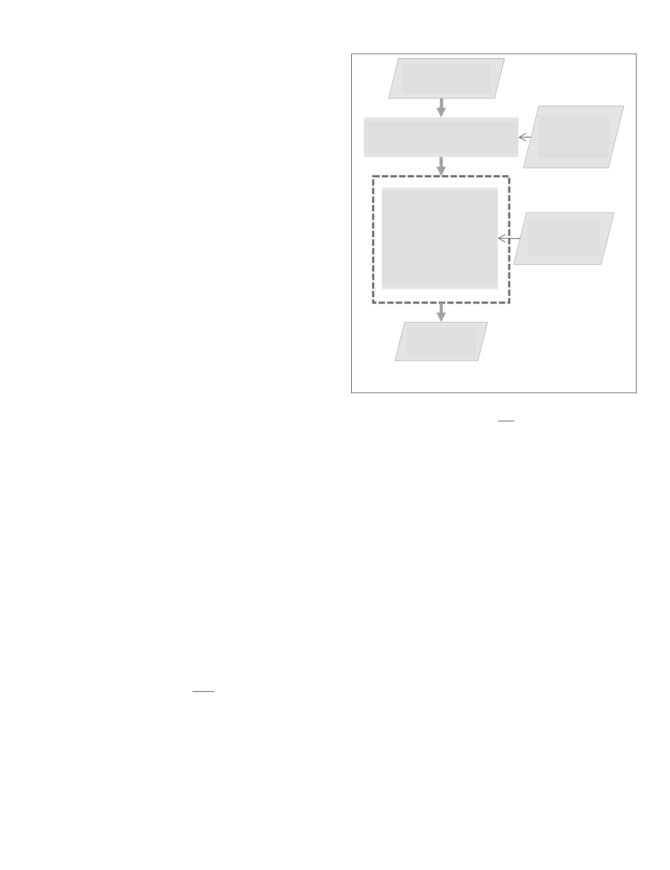
The image-based reflectance calibration process begins with
removal of path radiance from each pixel radiance using
dark object technique (Figure 1).
IAR
and
FAR
remove only
multiplicative component of atmospheric effects, and hence
separate correction is required before calibration to remove
the additive component that is path radiance. Once the addi-
tive component of atmospheric effects, that is path radiance,
is removed, the multiplicative component can be removed
by dividing each pixel by a suitable reference spectrum. The
average over all the pixels within an image or pixels over a
specific predefined area are considered to be reference spectra
for
IAR
and
FAR
, respectively (Figure 1). The improved dark
object technique,
IAR
, and
FAR
are described in the respective
sections below.
Improved Dark Object for Path Radiance Correction
Improved dark object technique (Chavez, 1988) (unlike dark
object technique) assumes that the relation between path radi-
ance and wavelength (atmospheric model) is different for dif-
ferent atmospheric conditions. To begin, the user selects the
model that best represents the atmospheric condition at the
time of data collection, and then selects a base path radiance
value from a selected channel using histogram (or predeter-
mined dark object). In the next step, path radiance for other
channels is calculated by scaling the selected path radiance.
The scaling factor is determined by the wavelength of the new
channel and the selected atmospheric model. For example,
for simple hypothetical model where path radiance is in-
versely proportional to wavelength, path radiance of channel
0.300 µm is 2.67 ({1/.300}/{1/.800}) times path radiance of
0.800 µm channel. The improved dark object technique has
been successfully used for Landsat data (Chavez, 1996). We
extended the approach to hyperspectral data wherein scaling
factors for each atmospheric model for all Hyperion channels
are calculated using band centers. Another option could have
been using Gaussian model of spectral response and removing
overlap between adjacent channels before extrapolating scal-
ing factors (Deshpande
et al
., 2014).
IAR and FAR
IAR
and
FAR
calculate the relative reflectance by dividing
each pixel in a given image by a calibration reference.
IAR
use
average spectrum over the entire image area for calibration,
whereas
FAR
uses average spectrum over a predetermined area
with certain desirable properties such as spectral blandness,
high reflectance: for example, a playa. The average spectrum
of total image area (
IAR
) in ideal situations where there is no
vegetation or any other dominant material in the scene, or a
given predefined area (in case of
FAR
), indicates absorptions
due to atmosphere, and hence can be used as a reference
spectrum to calculate the reflectance values.
Formally, for image of
m
rows and
n
columns with
k
bands:
IAR P
mxn
P
ij
i
i m
j
j n
ij
=
=
=
=
=
∑∑
( ) /
1
1 1
(1)
where,
P
ij
is a
k
dimensional pixel vector corresponding to
i
th
row and
j
th
column.
Now, consider
r
rows and
c
columns of known Flat Field
within the
m
×
n
image such that
0<r<m
and
0<c<n
, then Flat
Field Relative Reflectance (
FAR
),
FAR P
rxc
P
ij
i
i r
j
j c
ij
=
=
=
=
=
∑∑
( ) /
1
1 1
(2)
It is to be noted that flat field need not be regular shaped as
indicated by Equation 2.
Challenges
Though image-based methods are easy to implement, both
IAR
and
FAR
face certain challenges in urban conditions. If the
area under the study is covered with dominant feature having
a particular spectral characteristics, the
IAR
method is not
found to be suitable (Green
et al
., 1985). Modern urban spaces
are dominated by concrete, and hence the study needs to pay
attention to the image’s spatial coverage. Sufficiently large im-
age area outside the urban boundaries may reduce the domi-
nance of urban materials such as concrete. In case of doubtful
IAR
results, identifying flat fields within the scene becomes
critical to image-based methods and hybrid methods (Clark
et al
., 2002). Hybrid methods use flat fields within the scene
to remove residual atmospheric absorption and scattering
resulting from radiative transfer calibration procedure (Clark
et al
., 2002). Finding a flat field within the scene is critical for
other calibration methods also. The success of empirical line
method for reflectance calibration depends upon identifica-
tion of suitable flat field (Conel
et al
., 1987). Similarly, reflec-
tance based vicarious calibration method for a post-launch
sensor calibration requires identification of a flat field within
the scene (Slater
et al
., 1987; Slater
et al
., 1996; Secker
et al
.,
2001;Biggar
et al.
, 2003; Thome, 2004; NCAVEO, 2007).
There are two difficulties in finding an ideal flat field; find-
ing a flat field requires exploratory work because of lack of an
effective algorithm to do so. Zhang
et al
. (2003) attempted to
identify a flat field in a given scene automatically. As flat field
is considered to be proportional to average spectrum of a giv-
en scene, the approach suffers from all the drawbacks of
IAR
.
Another approach could be to compare spectral blandness
Candidate flat
fields
Reflectance
values
Remove path radiance using
dark object
Dark object
radiance
Divide each pixel by
flat field average
spectrum or average
spectrum of
complete image
Pixel radiance
Figure 1. Procedure for calculating reflectance of a pixel us-
ing empirical methods such as
IAR
and
FAR
.
PHOTOGRAMMETRIC ENGINEERING & REMOTE SENSING
May 2017
367


