In this work, due to integration with
INS
, none of the in-
troduced methods above are applied. Only the re-projection
of 3D features are needed to predict the pixel coordinates of
features. This is because the prediction of pixel coordinates of
features is differenced with measured coordinates to form the
measurement update in
EKF
, as mentioned before. In order to
re-project the 3D features on current image, the coordinates in
the world frame have to be transformed to current left camera
frame, given as:
X RX R feature T
c
w
w
=
=
−
(
)
(4)
where
R
is the rotation matrix transforming the vector in
world frame to current camera frame,
X
c
and
X
w
are the vector
from the perspective center to features expressed in current
camera frame and the world frame, respectively,
feature
w
is
the features coordinates expressed in the world frame,
T
is the
perspective center position in the world frame obtained by the
mechanization of
IMU
.
X
c
actually is the feature coordinates in
the current camera frame since the perspective center is the
origin of the camera frame. One thing needs to be explained
here is that the transformation between vectors just involves
the rotation, but in the calculation of the vectors, the transla-
tion has to be taken into consideration, which will be further
explained later in Equation 10. The world frame is a Cartesian
coordinate system, which is applied to uniformly denote the
coordinates of the platform and features. The features coordi-
nates in Equation 4 are obtained by triangulation of the stereo
cameras based on the simplified equation shown as:
X
Y
Z
u u B u u
v v B u u
fB u u
c
c
c
=
−
−
−
−
−
(
) / (
)
(
) / (
)
/ (
1 0
1 2
1 0
1 2
1 2
)
(5)
where
X
c
,
Y
c
, and
Z
c
are the feature coordinates in camera
frame namely
X
c
,
f
is the focal length,
u
0
and
v
0
are the pixel
coordinates of the perspective center projection on image,
B
is
the baseline length between the stereo cameras,
u
1
,
v
1
and
u
2
,
v
2
are the pixel coordinates of features on the rectified left and
right images.
With coordinates of the perspective center and the features
expressed in the world frame, the vector from perspective
center to the feature can be achieved in the world frame,
which has to be transformed to the current camera frame
using Equation 4. After transformation to the current camera
frame, the re-projection of the features in current camera
frame on the images (Hartley and Zisserman, 2003) can be
given as:
x
y
z
f
u
f v
X
Y
Z
u
v
c
c
c
=
0
0
0 0 1
0
0
=
x z
y z
/
/
(6)
where
X
c
,
Y
c
,
Z
c
,
u
0
,
v
0
, and
f
have the same meaning as Eqa-
tion 5,
u
and
v
are the pixel coordinates of features on the im-
age. The camera frame is defined as right, down, and forward
while the axel of the image frame are pointing to right and
down with the left up corner as origin. The camera and image
frames are illustrated in Figure 1.
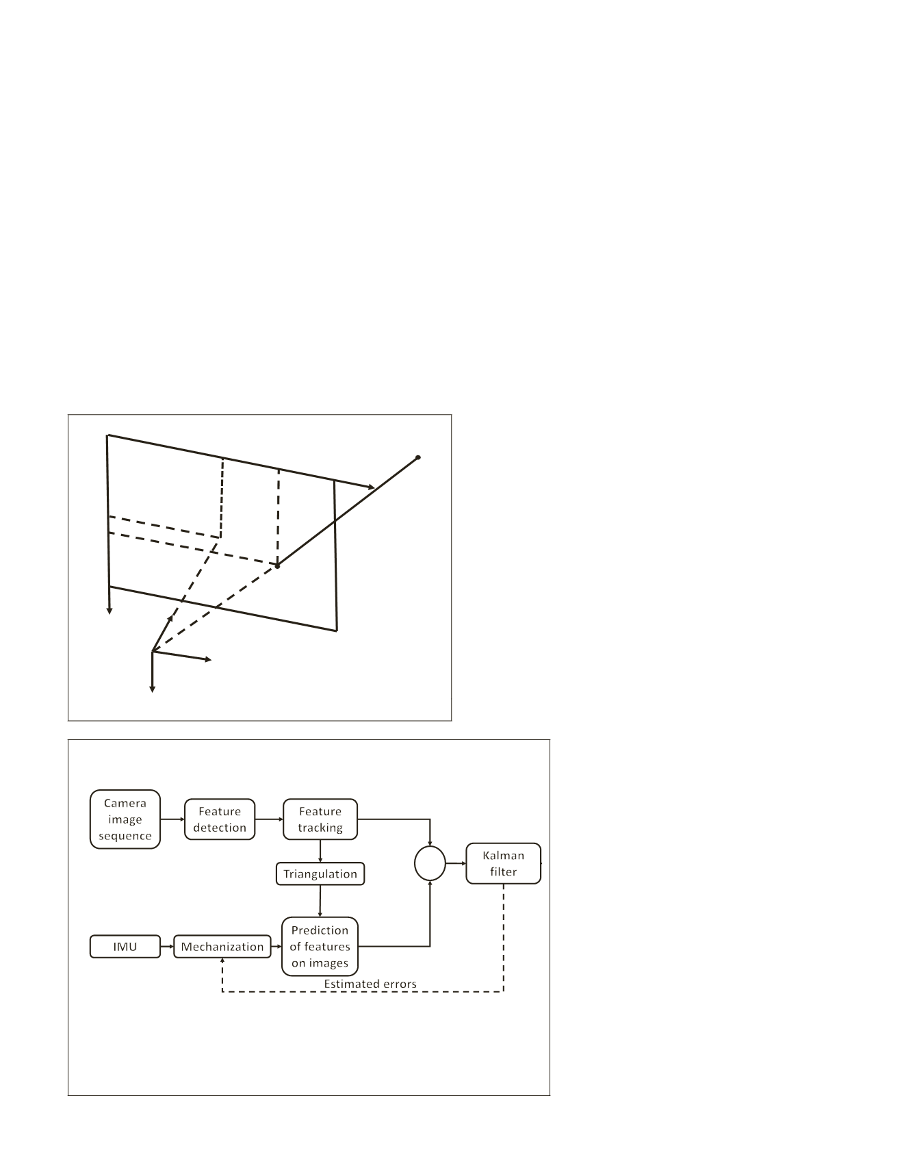
Tightly Coupled Integration of INS/Stereo VO
In the tightly coupled integration, an Extended Kalman filter
with conventional 15-parameter error-state
INS
system model is applied to fuse the inertial
and visual data. The mechanization outputs of
IMU
are the initial camera position and attitude
at current epoch, which is combined with the
triangulated feature coordinates at previous
epoch to conduct the re-projection of features
on current images. In this way, the pixel co-
ordinates of features on the current image are
predicted and then differenced with the mea-
sured pixel coordinates of features to form the
measurement update in the
EKF
. The procedure
is shown in Figure 2.
The implementation procedures of
EKF
are
presented as follows (Meinhold and Singpur-
walla, 1983).
X
X
P
P
GQG
K P H HP H R
k k k k
k
k k k k k
T
T
k k
T
k
T
−
− −
−
− −
−
−
−
=
=
+
=
+
Φ
Φ
Φ
,
,
,
(
)
1 1
1 1
1
−
−
−
−
−
= +
−
= −
1
1
X X K Z HX
P I K H P
k k k k
k
k
k k
(
)
(
)
(7)
(0,0)
x
y
C
(u
0
,v
0
)
P
(u,v)
X
Y
Z
Figure 1. Projection of features on image.
+
-
Figure 2. Tight integration implementation architecture. The Input of
the Kalman filter is the difference between the tracked and the predicted
features on the image. The prediction of the features on the image is the re-
projection of the features obtained by triangulation on the images based on
the camera position and attitude obtained by
IMU
mechanization.
PHOTOGRAMMETRIC ENGINEERING & REMOTE SENSING
January 2018
17


