3, the inputs for
SMP
-1 are
α
,
β
,
Δ
d
(
d
1
– d
2
), vertical gyro-rate
reading and HI (Heading Increment, namely the difference be-
tween the vehicle headings at consecutive epochs). The fuzzy
rules for
SMP
-1 can be summarized in Table 2 (Quddus, 2006).
This time, the likelihood is denoted as L2.
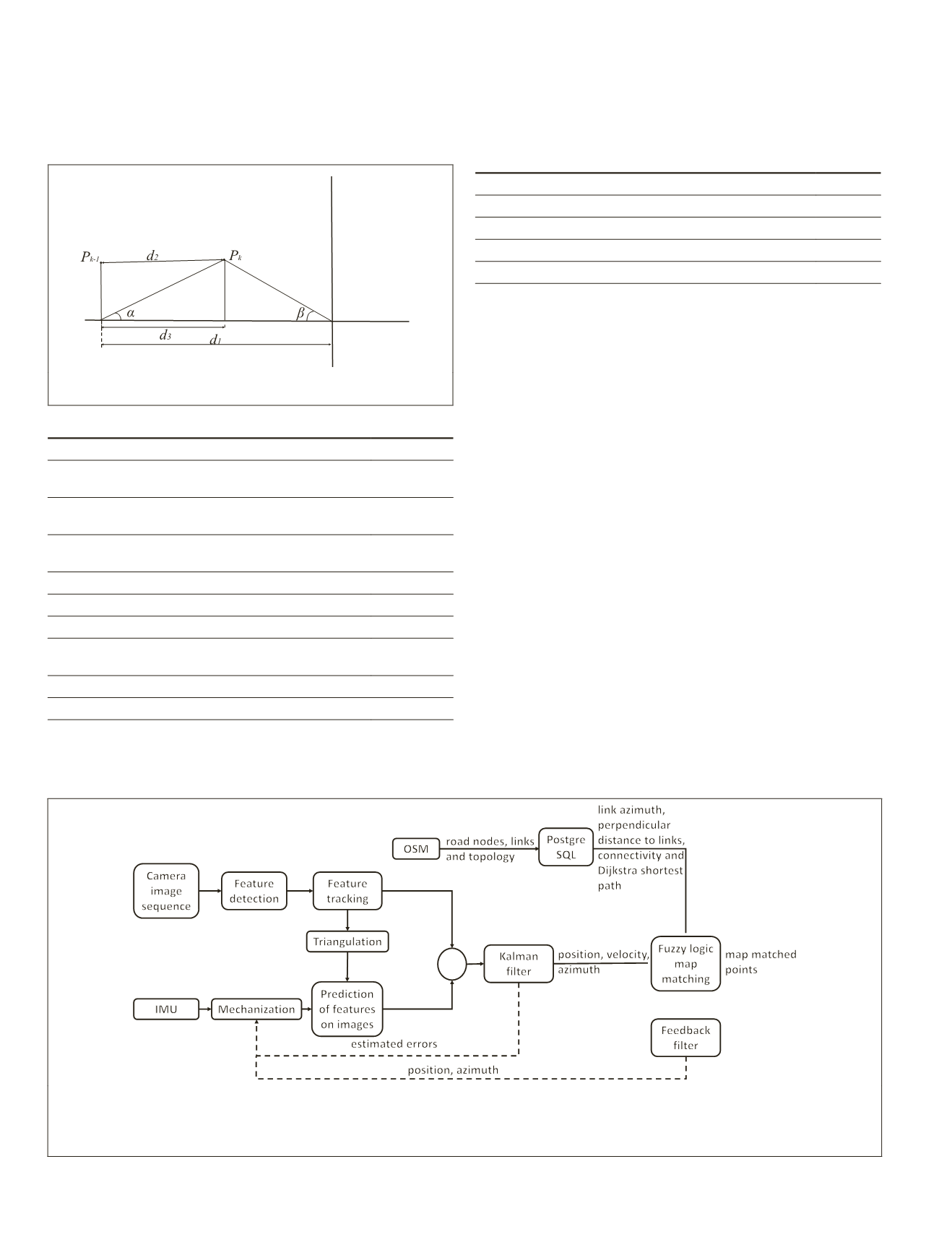
Figure 3. Parameters for fuzzy logic map matching (Quddus,
2006):
α
,
β
and d1- d2 are inputs for
SMP
-1.
Table 2. Fuzzy rules for
SMP
-1.
IF
THEN
α
is below 90 and
β
is below 90 and
the vertical gyro-rate reading is small
L2 is high
Δ
d
is positive and
α
is above 90 and the
vertical gyro-rate reading is small
L2 is low
Δ
d
is positive and
β
is above 90 and the
vertical gyro-rate reading is small
L2 is low
α
is below 90 and
β
is below 90 and HI is small
L2 is high
Δ
d
is positive and
α
is above 90 and HI is small
L2 is low
Δ
d
is positive and
β
is above 90 and HI is small
L2 is low
α
is below 90 and
β
is below 90 and the
vertical gyro-rate reading is high
L2 is low
α
is below 90 and
β
is below 90 and HI is large then
L2 is low
HI is small and
v
is high
L2 is average
The
SMP
-2 is activated when the vehicle is near the junction
or has just crossed the junction. This time, L3 is the likelihood
of matching the position fix to the link in
SMP
-2. In addition to
the fuzzy logic rules for
IMP
, there are four additional rules for
SMP
-2, which are listed in the Table 3 (Quddus, 2006). If the
selected link likelihood is smaller than a prescribed threshold,
the
MM
(Map Matching) goes to the
IMP
step.
Table 3. Fuzzy rules for
SMP
-2.
IF
THEN
the connectivity with the previous link is high
L3 is high
the connectivity with the previous link is low
L3 is low
the distance error is high
L3 is low
the distance error is low
L3 is high
Land Vehicle Localization Using INS,
Stereo VO and Map Matching
This paper proposes a new software framework to tightly
integrate
IMU
, stereo cameras, and digital maps. The overall
software system in divided into two parts: (a) integration of
IMU
and stereo cameras, and (b) Fuzzy logic based map matching,
which were previously explained in the first two sections of
this paper. The aim of the first part is to provide navigation so-
lution while the map matching part has two roles. The first role
is to identify the correct road link on which the vehicle moves
and to project the vehicle position on the selected road link
based on the integrated results and digital map information.
The second role is to reduce the drift error of the multi-sensor
by constraining the vehicle position on the road. Map match-
ing provides the feedback including the map matched position
and road link azimuth for
IMU
mechanization in next epoch to
reduce the drift of the integration of
IMU
and stereo cameras.
The OpenStreetMap (
OSM
) provides the digital map used
for map matching, which is the project that creates and dis-
tributes free geographic data for the world
streetmap.org
). An open source Relational DataBase Manage-
ment System (
RDBMS
) named PostgreSQL was used to load the
road link shape file, including information about road line
string geometry, start point, and end point position of each
road link, road link length and azimuth. The map matching
algorithm introduced in the previous section was connected
to PostgreSQL to manage the spatial queries. Dijkstra’s algo-
rithm (Johnson, 1973) is used to calculate the shortest path.
The implementation procedures are illustrated in Figure 4.
+
-
Figure 4. Tightly coupled integration of digital map and
INS
/Stereo
VO
. This figure is the expansion of Figure 2. The estimated
position, velocity, azimuth of
INS
/Stereo
VO
and the digital map information are used for fuzzy logic map matching. The map
matched point position and the road link azimuth are further applied as feedback to limit the quick drift of INS/Stereo
VO
. To
ensure the correctness of the feedbacks, a feedback filter is designed to remove mismatching.
20
January 2018
PHOTOGRAMMETRIC ENGINEERING & REMOTE SENSING


