in Lowe (1999). It is worthy to mention that our method is
conducted referring to the original image resolution without
an interpolation process and has potential to be combined
with other feature descriptors. The workflow of the proposed
method is depicted in Figure 1.
Figure 1. Block diagram of the proposed scheme.
Methodology
Considering the evaluations of feature descriptors in the
literature (e.g., Klette 2014; Chien
et al
., 2016), we leverage
SURF
to detect robust features and initialize the matching of
spherical images in this study. In addition, the transformation
between spherical and omnidirectional images described in
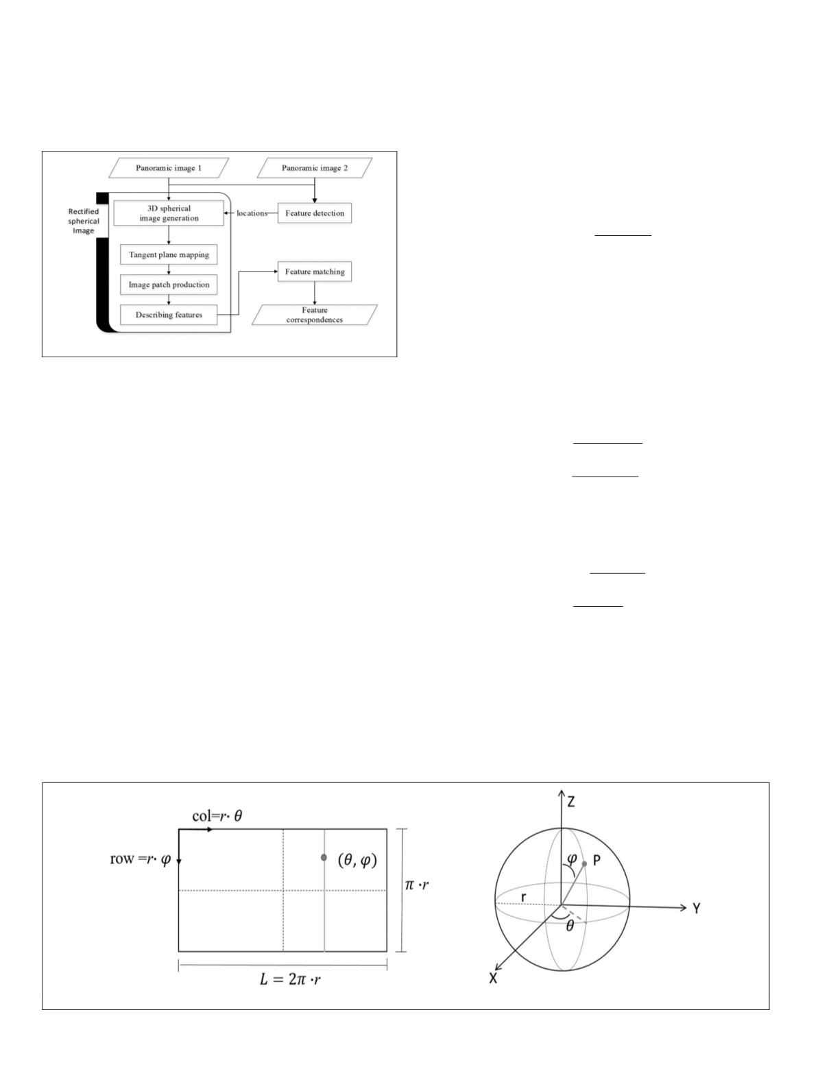
Fangi and Nardinocchi (2013) is shown in Figure 2, in which
r
is the radius of the sphere,
θ
is the longitude, and
φ
is the
complement of latitude. The transformation can be expressed
as Equations 1 and 2 (Fangi and Nardinocchi, 2013).
θ
φ
π
=
=
=
col r
row r
r L
/
/
/ 2
,
(1)
φ θ
φ θ
X r sin cos
Y r sin sin
Z r cos
=
=
=
φ
• •
• •
•
,
(2)
where (
col, row
) are image coordinates. Therefore, pixels of a
spherical image can be represented in 3D space as Cartesian
and spherical (
θ
,
φ
,
r
) coordinates.
Geometric Rectification for Spherical Matching
As illustrated in Figure 3, features in omnidirectional im-
ages are detected by
SURF
and converted to their spherical
coordinates using Equation 1. Small regions centered at each
detected point (
θ
i
,
φ
i
) are cropped from the sphere, respective-
ly. An angular range
d
derived from the scale
s
at which the
point was detected is used to determine the size of the region.
The pixels within the cropped region are mapped using an
orthographic projection onto the tangent plane that crosses its
feature point, in which the content of the plane is similar to
a perspective view with less distortion. Equation 3 describes
the orthographic projection of the points from the 3D cropped
region onto their tangent plane:
P P N
N P e
norm N
p
= −
+
*
( )
2
·
,
(3)
where
N
·
P
=
e
indicates a tangent plane.
N
is the normal
vector and
e
is the coefficient of the plane equation.
P
p
is
the point on the tangent plane mapped from the
P
= [
X Y Z
]
within the cropped region.
The tangent plane is then converted into a perspective
image patch. The size of the image patch (
S
row
,
S
col
) is com-
puted by Equation 4, where (
θ
max
,
θ
min
) and (
φ
max
,
φ
min
) are the
spherical coordinates of mapped extreme points, and
GSD
indicates the grid size, which is used to adjust the resolution
of the patch to coincide with the ground sampling distance of
the original image.
S
GSD
S
GSD
row
max min
col
max min
=
−
=
−
φ φ
θ
θ
,
(4)
The image coordinates (
row
p
,
col
p
) of each point
P
p
are de-
termined using Equation 5 where (
θ
i
,
φ
i
) indicate the spherical
coordinates of mapped points.
row
GSD
col
GSD
p
i
max
p
i
min
= − −
= −
φ φ
θ θ
.
(5)
The points on the tangent plane are projected to the nearest
grid in their corresponding image patch. Currently, we do not
refine these patches with hole-filling or interpolation process-
es to reduce computational burdens since the image patches
are intermediate outcomes. Subsequently,
SURF
is introduced
to assign feature orientation and describing features in these
image patches. The resulting descriptions are combined with
the locations traced back to the original panoramic images to
acquire complete
SURF
features. Finally, features are matched
between image pairs.
Figure 2. The relationship between equirectangular and spherical images.
26
January 2018
PHOTOGRAMMETRIC ENGINEERING & REMOTE SENSING


