to error covariances in 3
D
ground coordinate space without
needing detailed knowledge of the sensor operation itself.
This is made possible by defining a set of adjustable param-
eters in sensor space, and storing the uncertainties of these
parameters for future exploitation. The seven
general Sensor-
Space
ULEM
adjustable parameters
, described in the Stochas-
tic / Adjustment Model section, include:
• Corrections to sensor position (
Δ
x
,
Δ
y
,
Δ
z
)
• Corrections to sensor orientation (
θ
1
,
θ
2
,
θ
3
)
• Corrections to range (
Δ
r
).
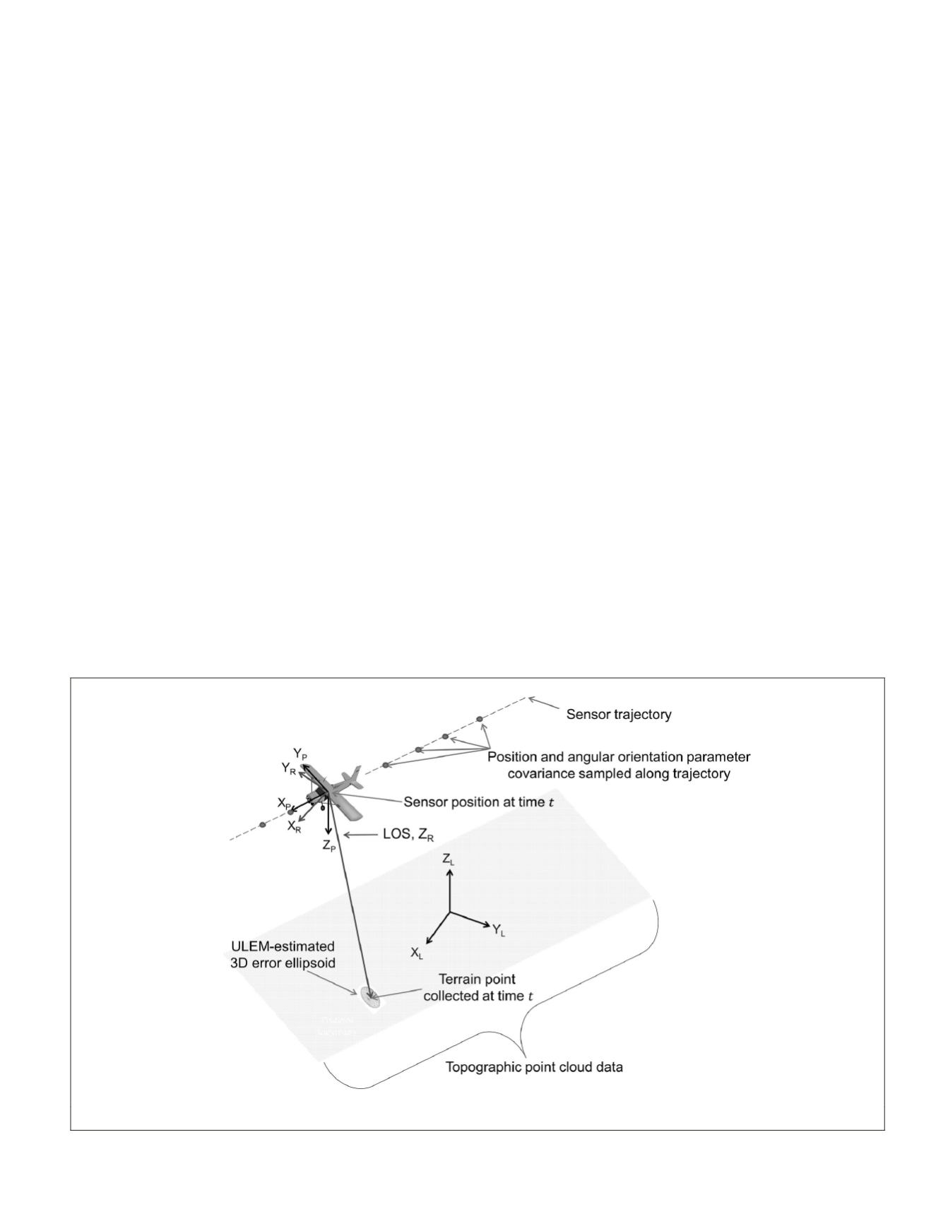
The Sensor-Space
ULEM
concept is illustrated in Figure 2.
Required Metadata and Definitions
The Sensor-Space
ULEM
concept involves requesting sufficient
metadata to approximately recreate the collection geometry.
To obtain the sensor position, metadata consisting of sensor
path (trajectory) samples (typically 3
D
coordinates in
WGS
84),
and associated timestamps must be provided. In addition, the
time and a unique sensor-path identifier associated with each
point’s measurement must be supplied. Given the sensor posi-
tion and terrain-point coordinates (related by respective time-
stamps and path identifiers), the estimated lidar line-of-sight
(
LOS
) vector can be calculated as shown in Figure 2. Note that
this construction is performed without the need for sensor
orientation measurements or range measurements, which
reduces the amount of data needed for subsequent process-
ing while maintaining sufficient geometry for error propaga-
tion. This
LOS
vector (i.e., range vector) is one key component
needed to estimate the measurement precision of the terrain
point. Once these basic components are obtained, three gener-
alized and consolidated coordinate systems are used to define
the approximated acquisition geometry: the
Local Coordinate
System
(
LCS
), the
Path Coordinate System
(
PCS
), and the
Ray
Coordinate System
(
RCS
).
The
LCS
used for Sensor-Space
ULEM
is a Cartesian coordi-
nate system, generally defined with its origin at a point of in-
terest (often the point being mensurated) or at the center of an
area of interest. It is an East - North - Up system. The positive
Z axis (+Z
L
) points upward along the ellipsoidal normal. The
positive X axis (+X
L
) is the cross-product of the ellipsoidal
North Pole and the positive Z axis (+Z
L
). The positive Y axis
(+Y
L
) is the cross-product of the positive Z axis (+Z
L
) and the
positive X axis (+X
L
), completing a right-handed Cartesian
coordinate system.
The
PCS
is established based on the sensor velocity vec-
tor associated with the epochs around the time of interest.
Establishment of this system is necessary for adjustment since
ULEM
does not carry detailed angular orientation informa-
tion. The
PCS
is uniquely defined for each specific epoch of
interest. The origin for this system is the instantaneous sensor
location as estimated from the trajectory information interpo-
lated at the epoch of interest. Its +X
P
axis is along the velocity
vector of the aircraft. The +Y
P
axis is the cross-product of the
PCS
+X
P
axis and the
LCS
+Z
L
axis. The +Z
P
axis is then the
cross-product of the
PCS
+X
P
and +Y
P
axes, completing a right-
handed Cartesian coordinate system.
The
PCS
and
LOS
enable the
RCS
. The origin for this system
coincides with the origin of the
PCS
. The
RCS
is also an or-
thogonal system with the +Z
R
axis defined along the estimated
LOS
and extending from the sensor location. The +Y
R
axis is
the cross product of the +Z
R
axis and the
PCS
+X
P
axis. The
+X
R
axis is then the cross product of the +Y
R
axis and the +Z
R
axis, completing a right-handed system.
Other key metadata needed to estimate the uncertainty
of the terrain points are the uncertainties associated with
the system measurement parameters. In the actual physi-
cal model, these uncertainties involve the various system
components, such as the
GPS
receiver, inertial measurement
unit (
IMU
), offsets and rotations between components, optical
component positions and angles, timing, etc. (Schenk, 2001;
Triglav-Cekada, 2009). The uncertainties will also be influ-
enced by the processing techniques used on the datasets. The
ULEM
concept involves combining these various individual
error contributors from the detailed physical model and rep-
resenting them as top-level
ULEM
parameters, namely:
Figure 2. The Sensor-Space
ulem
Concept.
PHOTOGRAMMETRIC ENGINEERING & REMOTE SENSING
July 2015
547


