each pixel is obtained by calculating the intersection point co-
ordinate of the
LOS
with the earth ellipsoid in
ECEF
coordinate
system, which can be described as follows without consider-
ing the influence of atmospheric refraction.
X X
Y Y
Z Z
M M M
ECEF
Orbit ECEF Body Orbit
Camera
−
−
−
=
0
0
0
2
2
2
µ
Body
y
x
Camera
−
tan
tan
( )
( )
ψ
ψ
1
(24)
where [tan(
ψ
y
) – tan(
ψ
x
) 1]
T
Camera
represents the detectors
LOS
vector in the camera coordinate system.
M
Camera2Body
repre-
sents the bias matrix of the camera coordinate system to the
attitude control coordinate system.
M
Body2Orbit
represents the
rotation matrix from the attitude control coordinate system
to satellite platform coordinate system.
M
Orbit2
ECEF
represents
the rotation matrix from orbit coordinate system to
ECEF
coordinate system.
μ
is a scalar. [
X
0
Y
0
Z
0
]
T
ECEF
represents
the satellite platform position interpolated by ephemeris at
imaging instant. [
X
0
Y
0
Z
0
]
T
ECEF
represents the
ECEF
coordi-
nate of the intersection point of
LOS
with the Earth ellipsoid.
During the in-orbit geometric calibration campaign, the preci-
sion instrument alignment angles in
M
Camera2Body
matrix and
LOS
vector [tan(
ψ
y
) – tan(
ψ
x
) 1]
T
in camera coordinate system
is periodically calibrated by referencing the global geometric
calibration sites.
From the analysis of atmospheric refraction effect on
geolocation, we draw the conclusion that the atmospheric
refraction will change the direction of
LOS
and result in
the geolocation error on earth spheroid. In the procedure
of DMC3/TripleSat Constellation direct georeferencing, the
detector’s
LOS
vector refractive deviation is subtracted from
the calibrated
LOS
vector in the camera coordinate system to
correct the atmospheric refraction geolocation error. When
the satellite operated in the roll and pitch imaging mode, the
collinear rigorous geometric model of Equation 24 is rewritten
as below:
X X
Y Y
Z Z
M
ECEF
ECEF Camera
y
pitch atm
−
−
−
=
−
−
0
0
0
2
µ
ψ ψ
tan(
_
os
x
roll atmos
Camera
)
(
)
_
tan
ψ ψ−
1
(25)
where
M
ECEF
2Camera
=
M
Orbit2
ECEF
M
Body2Orbit
M
Camera2Body
. (
ψ
x
,
ψ
y
) is
the interior orientation element in the camera coordinate sys-
tem,
ψ
roll_atmos
is the atmospheric refraction deviation angle rep-
resented in the camera coordinate system when the platform
rotation roll angle around the X axis,
ψ
pitch_atmos
is the atmo-
spheric refraction deviation angle represented in the camera
coordinate system when platform rotation pitch angle occurs
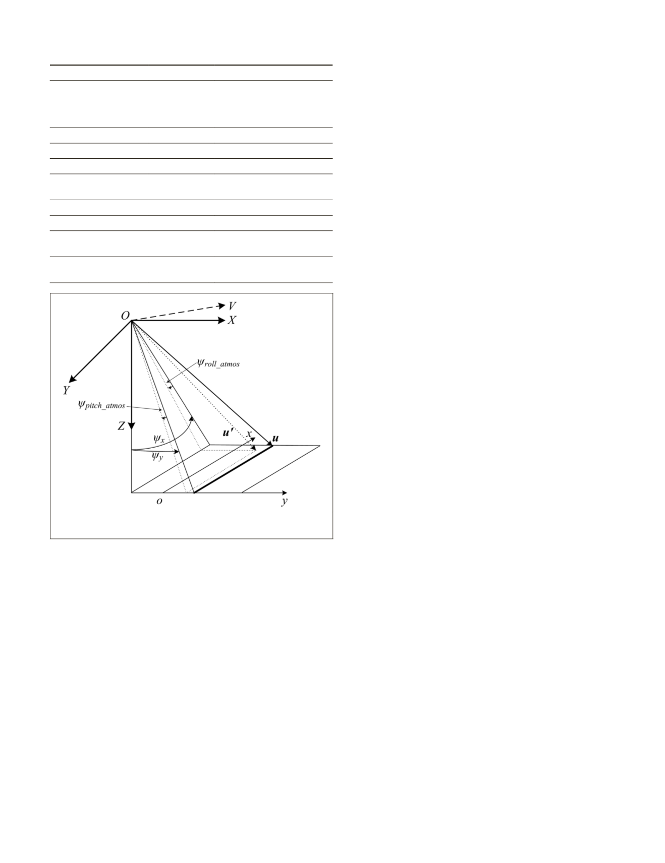
around the Y axis. The definition of the interior orientation
parameters is shown in Figure 8.
OXYZ
is the camera coordi-
nate system and
oxy
is the image coordinate system.
u
is the
LOS
vector in Equation 24.
u
′
is the
LOS
vector in Equation 25
by subtracting the atmospheric refraction deviation angle in
along and across track direction. In the DMC3/TripleSat Con-
stellation geometric model, the original points of the camera
coordinate system, body coordinate system, and orbit coordi-
nate system are in the same. The values of roll and pitch are
interpolated from the exterior orientation attitude parameters.
In the direct georeferencing of DMC3/TripleSat Constella-
tion images, the atmospheric refraction geolocation error was
transformed into the
LOS
deviation in the camera coordinate
system. And the atmospheric refraction geolocation error cor-
rection procedure is divided into 10 steps:
Step 1:
Use Equation 24 to calculate the
ECEF
coordinate
(
X,Y,Z
) of one pixel (
x,y
) by referencing
WGS84
ellipsoid.
Step 2:
Input the NASA Shuttle Radar Topographic Mission
(
SRTM
) global 90 m digital elevation data.
Step 3:
Transform the object’s
ECEF
coordinate (
X,Y, Z
) into
latitude and longitude.
Step 4:
Interpolate the roll and pitch value from exterior
orientation attitude parameters at the imaging instant. The
roll and pitch values are considered as the view angle of the
detector across and along track direction.
Step 5:
Use the simplified two layer atmosphere model and
terrain elevation to calculate the refraction index in strato-
sphere and troposphere. In the troposphere, there is a need to
calculate the refraction index between the terrain elevation
and the top of the troposphere.
Step 6:
Use the Equations 3 to 9 to calculate the
Δ
θ
roll
and
Δ
θ
pitch
across and along track direction on Earth’s surface.
Step 7:
Interpolate the spacecraft position (
X
0
,
Y
0
,
Z
0
) by using
ephemeris parameters at the imaging instant.
T
able
4. DMC3/T
riple
S
at
C
onstellation
C
apability
Sensor
Panchromatic
Multispectral
Band (μm)
0.45 to 0.65
Blue: 0.44 – 0.51
Green: 0.51 – 0.59
Red: 0.60 – 0.67
Near infrared: 0.76 – 0.91
GSD (m)
1
4
Swath (km)
24
24
Focal Length (m)
6.6667
6.6667
Detector
Dimension (μm)
10*10
40*10
Detector Number
6408*4
1602*4
Digitization (bit)
10
10
Max Off-pointing
(degree)
45
Imaging Mode
Stripe, Scene, Along track stereo,
Across track stereo and Area
Figure 8. Definition of interior orientation parameters with atmo-
spheric refraction geolocation error compensated.
PHOTOGRAMMETRIC ENGINEERING & REMOTE SENSING
June 2016
433


