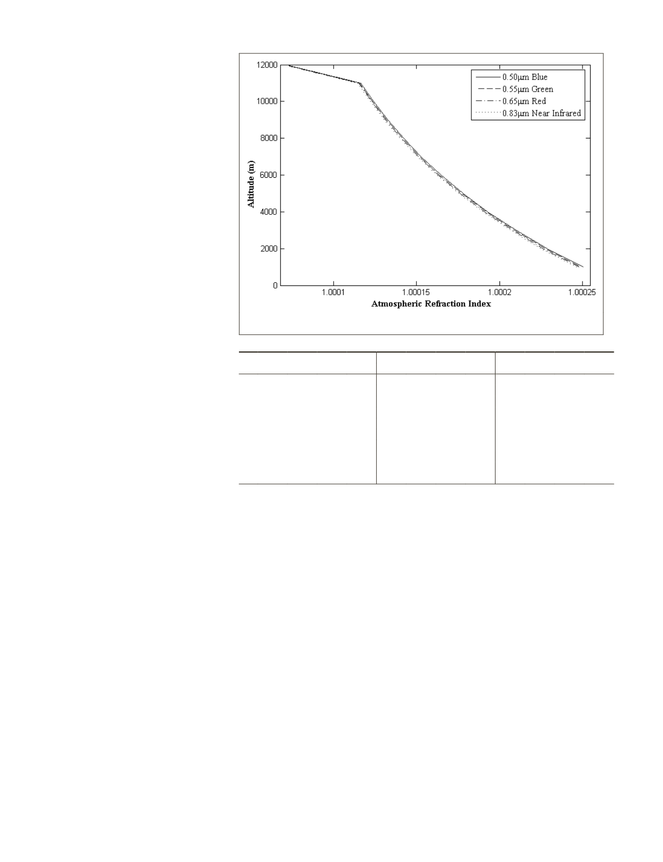
the atmospheric refraction index of blue
(0.5 μm), green (0.55 μm), red (0.65 μm),
and near-infrared (0.83 μm) monochromat-
ic light through the troposphere at N30°.
The shorter the wavelength, the larger of
atmospheric refraction index value. In the
following section, the atmospheric refrac-
tion geolocation error of the four mono-
chromatic lights will be analyzed.
Atmospheric Refraction Geolocation Error
When the satellite view angle
α
is known,
we can calculate the atmospheric refrac-
tion geolocation error on the ellipsoid
surface with zero altitude at any latitude.
Suppose the mean Earth radius
R
is
6,371 km, the altitude of satellite orbit
H
is 650 km, Table 3 lists the atmospheric
refraction geolocation error at N60°, N30°
and the Equator of blue (0.5 μm), green
(0.55 μm), red (0.65 μm) and near-infrared
(0.83 μm) monochromatic light in differ-
ent view angle of satellite in-orbit. In Table
3,
α
is the satellite off-pointing view angle,
Blu is blue band, Grn is green band, Red is
red band, and NIR is near-infrared band.
From Table 3, we can clearly observe
that the atmospheric refraction geolocation
error increases nonlinearly with the increas-
ing view angle. This conclusion is not only
confirmed by our proposed method, but also
verified by Noerdlinger (1999). Also, three
other conclusions as follows:
1. Atmospheric refraction geolocation
error is increased from the Equator
to South and North Poles.
2. Atmospheric refraction geolocation
error is increased with the shorter
of monochromatic light wavelength
in the same latitude. While, this
difference between blue, green, red, and near-infrared
bands are negligible. We will only use the green (0.55
μm) light to calculate the atmospheric refraction index
for high resolution optical satellite images direct geore-
ferencing.
3. Despite the fact that the atmospheric refraction geoloca-
tion error is not large, there is a need to correct this error
for the state-of-the-art high resolution satellite, such as
WorldView-3 (
GSD
: 0.31 m), GeoEye-2 (
GSD
: 0.34 m), Geo-
Eye-1 (
GSD
: 0.46 m) and WorldView-1/2 (
GSD
: 0.46 m).
Compared the atmospheric refraction geolocation error of
the proposed method with the results of Noerdlinger (1999),
Jaehong’s (Oh and Lee, 2011; Saastamoinen, 1972) and Ja-
cobsen’s (Jacobsen, 2004; Dowman
et al.
, 2012) methods, the
atmospheric refraction displacement is almost in the same
when the satellite was imaging inside the core of 20 degrees
around nadir. When the off-pointing angle is over 20 degrees,
the results of these methods are different. The authors believe
the Noerdlinger’s single layer spherically symmetrical atmo-
sphere assumption will result in the atmospheric refraction
index underestimated in the troposphere. And the Jaehong
and Jacobsen’s methods took the satellite altitude and the
object’s terrain elevation into account to calculate the atmo-
spheric refraction constant. These three methods were all not
considering the
LOS
path increased through the atmosphere
when optical satellite operated in off-pointing imaging mode.
Therefore, the larger of satellite off-pointing angle, the larger
value of the paper’s proposed method than Noerdlinger, Jae-
hong and Jacobsen’s methods.
Experiment on DMC3/TripleSat Constellation
The DMC3/TripleSat Constellation was launched on 10 July
2015 by a PSLV-XL launch vehicle from the Satish Dhawan
Space Centre, Sriharikota launch site in India. The constella-
tion was successfully delivered into a sun-synchronous orbit
with the local time of the ascending node of 10:30 at 651 km
altitude. The three satellites were phased 120 degrees apart
around the same orbit using their on-board propulsion sys-
tem. The DMC3/TripleSat Constellation satellites use the 450
kg SSTL-300S1 series platform, which provides 45 degrees
fast slew off-pointing and is capable of acquiring multiple
targets in one pass using multiple viewing modes. The high
resolution imager on board equipped with four Time-Delayed-
Integration (
TDI
)
CCD
arrays provides 1 m ground sampling
distance (
GSD
) in panchromatic and 4 m
GSD
in blue, green,
red and near-infrared multispectral mode with a swath width
of 24 km. The wide swath of the imager combined with agile
off-pointing capability enable the DMC3/TripleSat Constella-
tion to target anywhere on earth at least once a day. Table 4
lists the capability of DMC3/ TripleSat Constellation.
The DMC3/TripleSat Constellation linear pushbroom im-
ages are direct georeferenced by using the collinear rigorous
geometric model. The rigorous geometric model fixes the rela-
tionship between
LOS
vector in the camera coordinate system
with the
ECEF
coordinate system. The rigorous geolocation for
Figure 7. Atmospheric refraction index changes with different wavelength in tropo-
sphere at N30 degrees.
T
able
3. A
tmospheric
R
efraction
G
eolocation
E
rror
(U
nit
:
m
)
α
N60 Degree
N30 Degree
Equator
Blu Grn Red NIR Blu Grn Red NIR Blu Grn Red NIR
5° 0.24 0.24 0.24 0.24 0.23 0.23 0.23 0.23 0.23 0.23 0.22 0.22
10° 0.49 0.49 0.48 0.48 0.47 0.47 0.47 0.47 0.47 0.47 0.47 0.46
15° 0.78 0.78 0.77 0.77 0.76 0.76 0.75 0.75 0.75 0.75 0.75 0.74
20° 1.14 1.14 1.13 1.12 1.11 1.11 1.10 1.10 1.10 1.10 1.09 1.09
25° 1.62 1.62 1.60 1.59 1.58 1.57 1.56 1.55 1.56 1.56 1.55 1.54
30° 2.28 2.27 2.25 2.24 2.22 2.21 2.20 2.19 2.20 2.19 2.18 2.17
35° 3.26 3.25 3.23 3.21 3.18 3.17 3.15 3.13 3.15 3.14 3.12 3.10
40° 4.82 4.80 4.78 4.75 4.71 4.69 4.66 4.64 4.66 4.65 4.62 4.60
45° 7.56 7.53 7.49 7.45 7.38 7.35 7.31 7.27 7.31 7.28 7.24 7.20
50° 13.03 12.98 12.91 12.84 12.73 12.68 12.60 12.54 12.61 12.55 12.48 12.42
432
June 2016
PHOTOGRAMMETRIC ENGINEERING & REMOTE SENSING


