Usually, the above problems can be solved in two ways:
(1) by building permanent geometric calibration fields with
global coverage (e.g., SPOT (Valorge
et al
., 2003)) to ensure
the timely acquisition of cloudless images for calibration once
requested, and (2) accurately calibrating the orientation pa-
rameters according to the excellent agile maneuverability of a
satellite without the use of any control data of the calibration
fields (e.g., Pleiades; Kubik
et al
., 2012)). However, the first
method is both costly and time consuming, and the second
method requires very high satellite agility, which is not quite
feasible in practice. Therefore, some researchers attempted
the geometric integration of multiple satellite images to im-
prove the positioning accuracy without
GCPs
. Shengjun
et al
.
(2016) proposed the combined adjustment of multiresolution
satellite imagery; they used Pleiades-1 imagery to improve the
geopositioning accuracies of ZY-3 and SPOT-7 imagery from
16 to 5 m and from 6 to 2.5 m, respectively. In addition, a
similar tendency was observed in the improvement of the geo-
positioning accuracy for Cartosat-1 imagery through the use
of Worldview-1 imagery. Jeong
et al
. (2015) investigated the
positioning accuracy of image pairs, achieved by integrating
images from multiple satellites, including Ikonos, QuickBird,
and KOMPSAT-2 imagery. All available combinations were
analyzed to reveal the potential, limitations, and important
considerations for mapping applications by using images
from multiple satellites. Xutong
et al
. (2005) investigated the
integration of Ikonos and QuickBird images, and compared
the geopositioning accuracies of different combinations of
these images with different convergent angles. Rongxing
et al
.
(2008) presented another approach for improving the geopo-
sitioning accuracy of Ikonos and QuickBird imagery by using
aerial images acquired over the same region of Tampa Bay,
Florida. The results from these studies demonstrate that the
integration of images from multiple satellites can improve the
geopositioning accuracy of satellite images. However, all of
the aforementioned studies primarily focused on geometric
integration for block adjustment based on the rational func-
tion model (
RFM
) and mainly considered the compensation
of exterior errors; the stable interior orientation parameters
of satellites cannot be recovered to ensure the geopositioning
accuracies of the basic products.
In this paper, a geometric cross-calibration method is pro-
posed, which is similar to the principle of cross-calibration in
the field of radiometric calibration (Gyanesh
et al
., 2013). This
method first extracts conjugate points from the multitemporal
images of one satellite or multi-satellite images. Then, it re-
covers the interior orientation parameters precisely based on
the geometric restriction that the conjugate points should be
positioned at the same location. In contrast to the convention-
al geometric calibration method, the proposed method does
not rely on the control data of the calibration fields. Thus, the
satellite’s geometric parameters can be accurately calibrated
with global images from Worldview, GeoEye, Pleiades, etc.,
once it is launched, without the need to scan the calibration
fields. The multitemporal images of the Yaogan-4 satellite and
the images of the ZY3-01 and ZY02C satellites were consid-
ered for verifying this method. Finally, the proposed and con-
ventional methods achieved accuracies of approximately 0.7
and 0.6 pixels, respectively; this shows a difference of only
approximately 0.1 pixels between the methods, demonstrating
that the proposed method can achieve a calibration accuracy
as high as that achieved by the conventional method, even
without the use of high-accuracy control data.
Methodology
Principles of Geometric Cross-Calibration
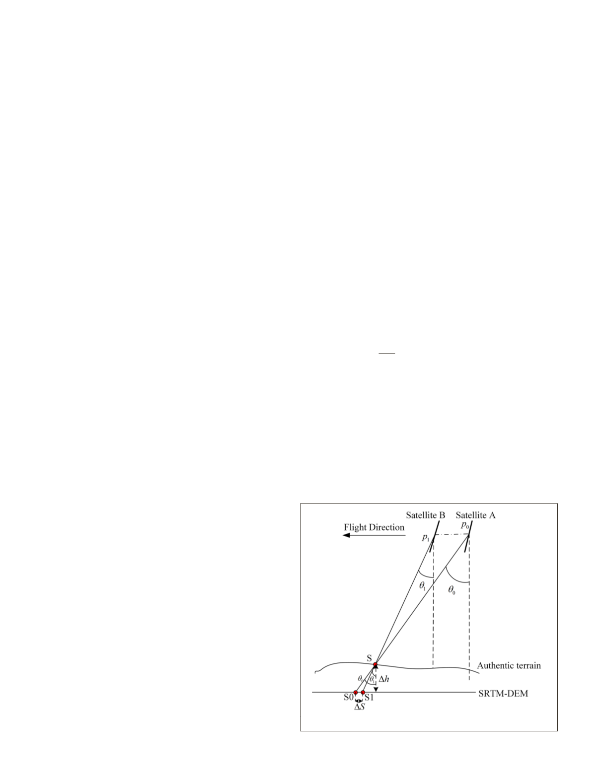
Geometric cross-calibration requires two satellites scanning
the same area. As shown in Figure1, satellites A and B image
the same ground object S at pixels
p
0
and
p
1
, respectively,
with imaging angles of
θ
0
and
θ
1
, and
Δ
h
is the elevation error
of the global open Shuttle Radar Topography Mission data
(
SRTM
-
DEM
) at S.
If it is assumed that there is no error in the orientation
parameters (including the measured orbit, attitude, and
interior orientation parameters) of satellites A and B, and the
elevation of S is correct, the conjugate points
p
0
and
p
1
should
be positioned at the same location S in Figure 1. However,
it is often difficult to locate
p
0
and
p
1
at the same point on
the ground because of errors in orientation parameters and
the stereoscopy error induced by the elevation error
Δ
h
of S.
While only considering the elevation error
Δ
h
of S as shown
in Figure 1, the conjugate points
p
0
and
p
1
should be posi-
tioned at S0 and S1, respectively, with
SRTM
-
DEM
, and the
deviation between S0 and S1 can be approximately calculated
as follows:
Δ
S
=
Δ
h
(tan
θ
1
– tan
θ
0
)
(1)
Based on Equation 1, when
θ
0
and
θ
1
are sufficiently close
(i.e., the two satellites scan one region with very similar atti-
tude angles),
Δ
S caused by the elevation error can be neglect-
ed. In practicality, the maximum difference between
θ
0
and
θ
1
can be determined based on the required calibration accuracy
as (tan
θ
1
– tan
θ
0
)<
δ
cal
h
∆
, where
δ
cal
denotes the required
calibration accuracy.
In this case,
Δ
S
is only caused by the exterior and inte-
rior errors, and it can be calculated by
Δ
S
i
=
g
(
x, y
) +
f
A
(
p
i
) –
f
B
(
q
i
)
(2)
where
g
(
x
,
y
) represents the deviation in the intersection
induced by exterior errors, and
f
A
and
f
B
denote the interior er-
rors of satellites A and B, respectively. If the interior orienta-
tion parameters of satellite A have been accurately calibrated
(i.e.,
f
A
≈
0), Equation 2 can be written as
Δ
S
i
=
g
(
x, y
) –
f
B
(
q
i
).
(3)
Figure 1. Schematic of the intersection of conjugate points.
486
August 2018
PHOTOGRAMMETRIC ENGINEERING & REMOTE SENSING


