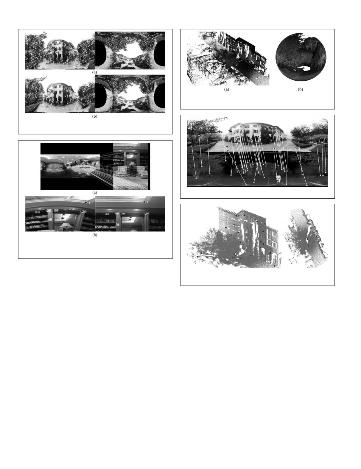
Figure 8. 3D point cloud from terrestrial LIDAR where (a)
Panoramic point cloud; and (b) Sphere of 3D points.
Figure 9. Results of matching between panoramic image and lidar.
Figure 10. Corresponding points and the center of the
spherical panoramic image.
we implement the rectified spherical matching to simplify the
current working scheme. As shown in Figure 8, the PENTAX
P-1000 laser scanner is applied to collect 360° point cloud
of the same scene in Figure 4 but at a different viewpoint
and time. The total number of points in this point cloud is
3,891,953. This point data are then transformed into a spheri-
cal coordinate system and form a sphere based on the aver-
age radius of points. The radius is constant and determined
according to the demanded resolution.
In this case, we form the intensity image with the same
size of Figure 4 and normalize the image content of these two
panoramic images for matching. Similarly, to collect more re-
liable point matches, rigorous thresholds as mentioned above
are applied to the Fast-Hessian detector of
SURF
and the ratio
test. The matching result is inspected by a manual check.
Figure 9 shows the matched point pairs where the correct
rate is about 64 percent. Apparently, the number of matched
points is less than that matching with conventional images,
since the data source are different in essence. Figure 10 depicts
the matched features superimposed onto the point cloud in
which the point cloud is sparse for better illustration.
It can be observed that the resulting 2D-to-3D correspon-
dences are well distributed in this scene, and we performed
resection in space to estimate the absolute pose of the camera.
Yet, the resulting position accuracy of the camera center
reflects an
RMS
of 3.34 cm. It can be understood that the lidar
point cloud has been down-sampled and smoothed to gener-
ate the panoramic intensity image. Thus, the quality of ob-
served points is deteriorated influencing the accuracy of the
camera pose estimation. Nevertheless, the rectified spherical
matching largely simplify the conventional automated way of
obtaining 2D-to-3D correspondences, and the results can be
treated as approximations for further refinement.
Pose Estimation of Spherical Image Sequences
In addition, the proposed rectified spherical image matching
can be used as a component within a scheme of sequential
image pose estimation (structure-from-motion,
SfM
). In this
case, we collect 49 spherical panoramic images with a size of
5,376 × 2,688 pixels in an indoor environment. For an insight
into the proposed method, we apply
SURF
,
PR+SIFT
, and the
rectified matching to a pipeline similar to Torii
et al
. (2009).
Furthermore, we increase the baselines between images by
reducing the number of cameras to assess merits contributed
by the wide field of view of panoramic images. The object
function for camera pose estimation can be read as:
x
L
C
T
ECx
R
T
= 0,
(6)
where
x
L
and
x
R
indicate the image coordinates of each image,
and
C
is the matrix conveying interior parameters of the cam-
era.
E
is the essential matrix which can be solved linearly and
used as approximations for nonlinear least squares adjust-
ment (Mikhail and Ackermann, 1976; Longuet-Higgins 1981).
Figure 6. Distribution of point matches where (a) Proposed
method (8,289 pts);and (b) SURF (6,195 pts).
Figure 7. Matching between panoramic and planar images
where (a) Matching between equirectangular and planar
images; and (b) Magnified region of region A.
30
January 2018
PHOTOGRAMMETRIC ENGINEERING & REMOTE SENSING


