they initially try to learn the offsets between the clocks of
all devices. Afterwards, they use a second method to deter-
mine the transport delays. For this purpose they evaluate the
“crispness” of resulting point clouds using different criteria
than us. A further distinction is that our approach focuses on
one laser scanner only, and thus it is not required to employ
two separate algorithms to detect the offset.
Rehder
et al
. (2016) present a general approach to achieve
a spatiotemporal calibration in multi-sensor systems. Their
method employs a continuous-time batch estimation that does
not rely on certain properties of specific sensors. Thereby,
they are able to estimate the temporal offset between various
sensor combinations. The authors show the usefulness of
their approach by determining the timestamp offset between
camera, IMU, and laser scanner. Similar to our approach, they
assume that the clocks of the sensors are delayed by constant
timestamp offsets that arise due to effects such as transmis-
sion delays or signal integration. However, they propose a
fundamentally different method which uses different criteria
and is computationally expensive. Furthermore, their ap-
proach cannot be used to estimate temporal offsets between
an actuated laser scanner and its corresponding motor.
The remainder of this paper is organized as follows. First,
the sensor system we used to evaluate the methods presented
within this paper is introduced followed by our approach
to calculate the timestamp offset between the laser scanner,
motor, and camera. Since we developed two independent
methods, this section is divided into two subsections: one for
the stationary approach that calculates the offset prior to data
acquisition and one for the approach that deals with large
datasets. Experiments demonstrating both methods are then
presented for a number of datasets of different characteristics.
Subsequently, we analyze and discuss the results of our ex-
periments, and finally, give a conclusion and future work.
System Overview
The idea of this paper is validated on a sensor system con-
sisting of a Hokuyo UTM-30LX laser scanner that is actu-
ated by a Dynamixel MX-64R motor, and a Microsoft Kinect
v2. The laser scanner can provide a 2D scan with a field of
view of 270° and an angular resolution of 0.25°. However, for
our experiments the field of view is limited to 180° to avoid
detection of the frame the laser scanner is attached to. Every
measurement of the laser scanner takes 25 ms which leads to
a scan frequency of 40 lines/sec. Furthermore, the laser scan-
ner has a maximum detection range of 30 m and a minimum
detection range of 0.1 m.
The Dynamixel MX-64R robot actuator is able to operate at
an angle of 360° or at a continuous turn. Besides, the motor
supports the measurement of its own position and speed. For
this, it provides an angular resolution of 0.088°. To control the
motion of the actuator we use the Dynamixel motor package
that is available for the Robot Operating System (
ROS
).
The Microsoft Kinect v2 depth-sensing camera provides
RGB
(1920 × 1080 pixels, 30 fps), depth (512 × 424 pixels, 30
fps) and active
IR
images (512 × 424 pixels, 30 fps). Our cam-
era’s focal length is roughly 267 pixels, and it covers a field of
view of 70° × 60°.
Unfortunately, Microsoft has not released information
about the dimension of the
RGB
camera sensor. For this work
we only use the
RGB
stream with a resolution of 480 × 270
pixels and 10 fps. The typical distance to objects that we use
as features for our visual odometry is 2 to 20 meters.
We determine the camera’s intrinsic parameters using
the algorithm proposed by Z. Zhang (2000) and its imple-
mentation in the Open Source Computer Vision Library
(
OpenCV
). We consider two parameters for the focal length, two
parameters for the principal point and three parameters for
the radial distortion. We do not determine the tangential dis-
tortion parameters since they show no effect for the Microsoft
Kinect v2.
The laser scanner and the motor are connected to a Kon-
tron KTQM87 based embedded
PC
which runs the motion
controller for the actuator. Moreover, the embedded
PC
col-
lects the measurement data from the laser scanner as well as
the position data from the motor and assigns timestamps to
them. Due to latency and transmission lags of sensors and the
embedded
PC
, these timestamps may be delayed by a constant
offset that needs to be determined.
It is important to note that the devices are attached to dif-
ferent ports of the embedded
PC
. While the motor is connect-
ed to the
USB
port using a
USB
to RS485 converter, the laser
scanner is attached to the
LAN
port. Thus, our assumption
about a constant offset remains valid since both devices do
not interfere with the measurement data acquisition of each
other due to the utilization of different ports. Additionally,
our embedded
PC
does not operate at full computational load
which further ensures a constant timestamp offset.
The Microsoft Kinect v2 is connected to Nvidia’s Tegra-
based Jetson TK1 embedded board to the
USB
. To synchronize
the clocks of the Kontron
PC
and the Tegra board, we use the
Network Time Protocol (
NTP
) (Mills, 1991). However, an offset
between the laser scanner’s and the camera’s timestamps still
remains, since there are transmission delays from each sensor
to the system it is attached to. Furthermore, we do not expect
NTP
to work perfectly which introduces another source for
possible timestamp offsets.
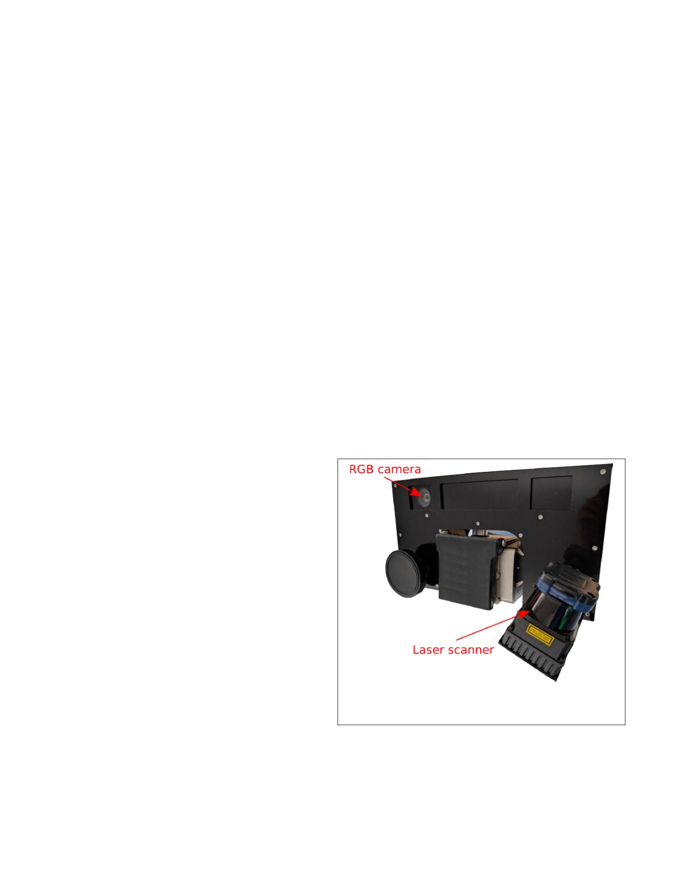
Our multi-sensor system can be seen in Figure 1. For our
experiments we focused on the rolling scan method for which
the laser scanner is rotated around its center. This gives the
advantage of only one focus point in front of the laser scanner
(Wulf and Wagner, 2003).
Figure 1. Our multi-sensor system consists of a Microsoft
Kinect v2 and a Hokuyo UTM-30LX scanning laser range-
finder that is rotated by a Dynamixel MX-64R robot actuator.
The motor is set to control the laser scanner such that a
sweep lasts 0.5 s, where a sweep is the rotation from −90° to
+90° or in the inverse direction with the horizontal orienta-
tion as 0°. This yields a rotation frequency of 1
Hz
since a
sweep is half a full rotation. The frequency at which a com-
plete 3D scan is acquired amounts to 2
Hz
.
358
June 2018
PHOTOGRAMMETRIC ENGINEERING & REMOTE SENSING


