computers continuously, and thus needs a long lead time
until the synchronization is accurate. We were not able to
record all datasets in a row, but rather had to shut down both
the Kontron
PC
and the Tegra board in between our measure-
ments. Thus, upon restart the clocks had to be synchronized
again using
NTP
which may have led to different timestamp
offsets between both systems, and, consequently, between
both sensors. We do not face this problem for the laser scan-
ner to motor synchronization since both sensors are attached
to the same computer. To obtain a constant timestamp offset
between laser scanner and camera, it would be advisable to
connect both sensors to a common computer with enough
processing power to handle both sensor’s datastreams.
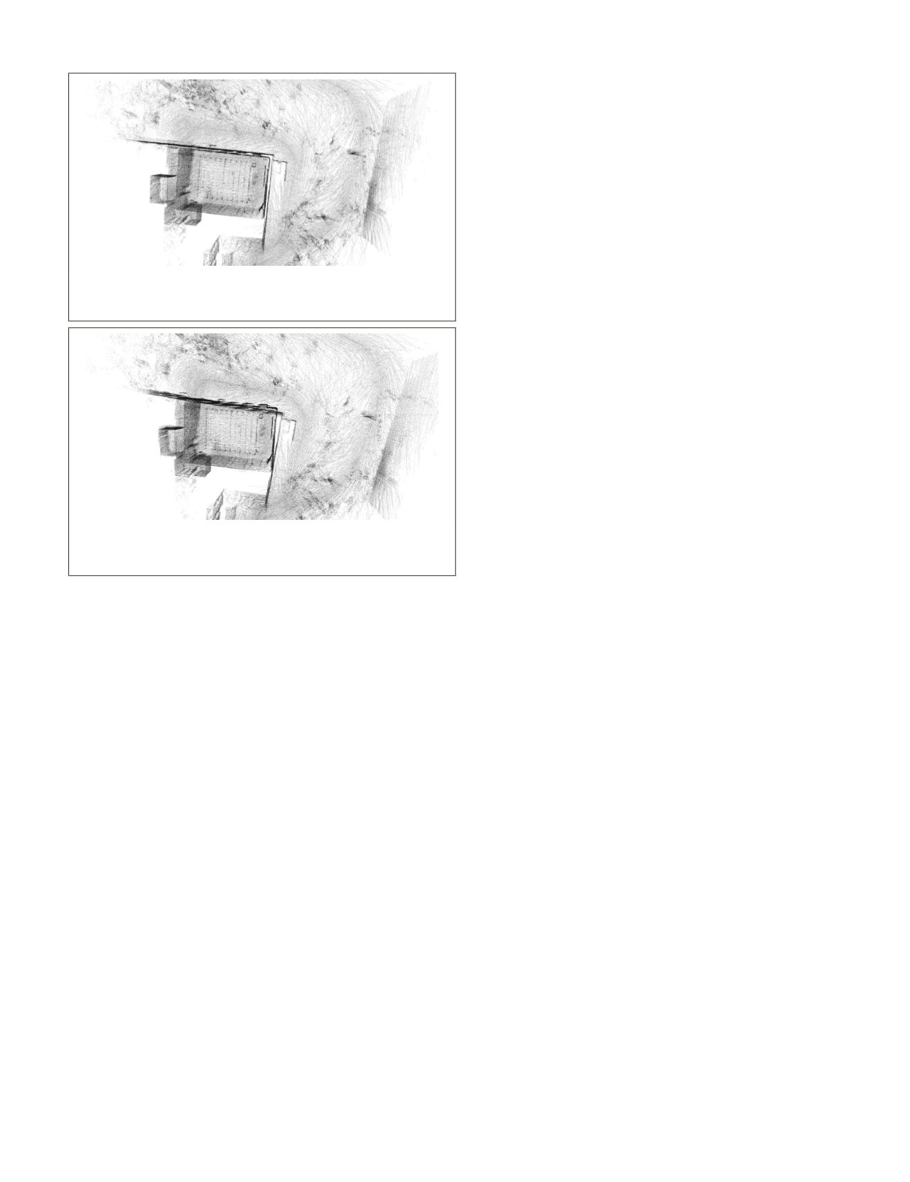
Similarly as for the laser scanner to motor synchronization,
we show the influence of an inappropriate timestamp offset
between laser scanner and camera by comparing the same
map section for two different offsets. Both figures show the
lecture room in top view and some parts of its surroundings.
To create those maps, we carried our multi-sensor system
through the lecture room at first and then took a walk around
the building. We chose an appropriate timestamp offset of 100
ms for Figure 11, and thus it can be seen that the inner and
outer walls of the room align perfectly parallel. In contrast to
that, the inner and outer walls in Figure 12 are not parallel
since we chose an inappropriate timestamp offset of 180 ms.
However, the local clarity - which is the clarity for indi-
vidual, small parts of the map (e.g., the clarity of the outer
wall) - in Figure 12 is comparable to that in Figure 11. This
is in contrast to the laser scanner to motor synchronization
where the local clarity decreases for an inappropriate time-
stamp offset (cf. Figure 10). One possible explanation for
these observations could be that the
SLAM
approach does not
need an accurate initial motion estimation from the visual
odometry to produce locally accurate results. For the global
motion estimation, however, it needs these initial motion es-
timations to be correct in order to find the correct matches in
the lidar odometry algorithm. In summary, it can be said that
the timestamp offset between laser scanner and camera needs
to be determined appropriately to generate accurate results.
Conclusions and Future Work
Incorrect synchronization for a multi-sensor system can lead
to an erroneous motion estimation and distortion in the re-
sulting point clouds when using it to solve the
SLAM
problem.
To solve the problem of synchronization between an actuated
laser scanner and its motor we presented two independent ap-
proaches to calculate the timestamp offset between these two
devices. Both use different parts of a
SLAM
approach proposed
by J. Zhang and Singh (2015) and distinct criteria to find an
appropriate offset. Moreover, our motion-based approach can
be further used to find the timestamp offset between a laser
scanner and a camera.
Our experiments have shown that both approaches yield
similar results within an accuracy of 1 ms for the laser scan-
ner to motor synchronization. However, the experimental
results also showed that an accuracy of 1 ms is sufficient.
Thus, it can be stated that both methods are convenient to
determine the desired offset. Furthermore, we managed to
find an appropriate timestamp offset between laser scan-
ner and camera using our motion-based approach, and thus
think that the underlying idea can be used for arbitrary sensor
combinations. However, it should be noted that different
experimental setups might yield different accuracies for the
timestamp offset if the distance to objects and the robot’s
movement characteristics vary from our experiments. Finally,
we were able to demonstrate the negative effect an incorrect
synchronization within our multi-sensor system can have on
the resulting point clouds and the motion estimation.
Future work involves applying the motion-based approach
to other sensor combinations that are fused in a similar
SLAM
approach. Additionally, an approach similar to our stationary
method should be developed especially for the laser scanner
to camera synchronization in order to provide a reference to
results from the motion-based approach. Moreover, we plan to
find out why the timestamp offset between laser scanner and
camera was not constant across all datasets. Finally, we aim
to make precise statements about our approach’s accuracy by
evaluating the slope of our fitted polynomials and examine
which influence the distance to objects and the robot’s move-
ment characteristics have on the accuracy.
Acknowledgments
This work was supported by the German Research Foundation
(
DFG
) as part of the Research Training Group i.c.sens [
RTG
2159].
References
Bosse, M., and R. Zlot, 2009. Continuous 3D scan-matching with a
spinning 2D laser,
Proceedings of IEEE International Conference
on Robotics and Automation 2009
, May 2009, Kobe, Japan, pp.
4312–4319.
Bosse, M., R. Zlot, and P. Flick, 2012. Zebedee: Design of a Spring-
Mounted 3D Range Sensor with Application to Mobile Mapping,
IEEE Transactions on Robotics
, 28(5):1104–1119.
Droeschel, D., J. Stuckler, and S. Behnke, 2014. Local multi-resolution
representation for 6D motion estimation and mapping with a
continuously rotating 3D laser scanner,
Proceedings of IEEE
International Conference on Robotics and Automation 2014
,
May 2009, Hong Kong, China, pp. 5221–5226.
Figure 11. Map section generated by the
SLAM
approach for
the lecture room dataset using an appropriate timestamp
offset between laser scanner and camera of 100 ms.
Figure 12. Map section generated by the
SLAM
approach for
the lecture room dataset using an inappropriate timestamp
offset between laser scanner and camera of 180 ms.
PHOTOGRAMMETRIC ENGINEERING & REMOTE SENSING
June 2018
365


