Afterwards, the sweep to sweep refinement determines the
motion of the laser scanner by matching extracted edge points
to edges and planar points to planar patches from the previ-
ous sweep. Subsequently, an optimization algorithm is used
to minimize the distance between the correspondences.
The second algorithm (sweep to map registration) is
responsible for matching the edge points and planar points
from the last sweep onto the global map. Thereby, the second
algorithm is able to correct for drift over time. An example for
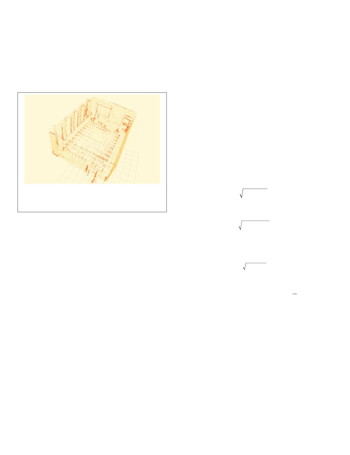
a map can be seen in Figure 4.
Figure 4. An example of a map that is used within the
sweep to map registration. Dark orange points were
extracted as edge points while light orange points were
extracted as planar points.
To register an edge point from the most recent sweep onto
the map, the algorithm finds edge points within a certain
region around the newly extracted edge point in the map and
fits an edge through them. In a similar way, the correspond-
ing planar patch for a planar point is determined. Afterwards,
both feature types are combined in an optimization algorithm
to minimize the distance from edge points to corresponding
edges and from planar points to corresponding planar patches.
For the lidar odometry algorithm to work, it is essential
to detect enough edges and planar patches. However, if these
feature points are missing for a short period of time only, the
visual odometry motion estimation that is used as an input for
the lidar odometry algorithm is capable of compensating the
absent laser feature points. Similarly, if no visual features are
available to estimate the motion in the visual odometry algo-
rithm, the lidar odometry algorithm can still work. However,
if the visual odometry fails while performing rapid move-
ments (especially rotations) the lidar odometry algorithm will
not be able to recover. Although visual and laser scan features
were missing for short periods of time for all our datasets, the
motion estimation algorithm was able to perform well. To ob-
tain a reasonable motion estimation (and therefore a reliable
timestamp offset) we advise to obtain data in environments
which allow the laser scanner to observe at least two perpen-
dicular edges and one planar patch at all times. Addition-
ally, it is important for the visual odometry algorithm to find
features that are distributed across the entire image.
Stationary Approach Prior to Data Acquisition for Online Computations
To compute the offset between the timestamps of the laser
scanner and the motor, the system is set up as follows. The
motor is set to rotate the laser scanner at a constant angular
velocity around the center of the scanner. Subsequently, the
devices are brought into a fixed position and required to
remain in place until a short dataset is recorded.
The idea is to determine the offset that leads to the small-
est movement calculated by a
SLAM
approach that incorpo-
rates the desired time offset between the timestamps of the
laser scanner and the motor. Since the system remains station-
ary for the computation, the movement calculated by a
SLAM
approach should be zero. However, due to transformation
errors caused by a false timestamp offset the 3D data points
do not match perfectly from one sweep to another and lead
to erroneously computed movements by the
SLAM
algorithm.
This is because consecutive sweeps are acquired in oppo-
site directions. We use parts of the lidar odometry algorithm
proposed by J. Zhang and Singh (2014) that was introduced in
the previous subsection.
Since our system will not move within the map, we ex-
clusively use the sweep to sweep refinement which has the
important characteristic that it matches consecutive sweeps
acquired in opposite directions (for one sweep the laser scan-
ner is rotated from –90° to 90° and for the following sweep
the scanner is rotated from 90° to –90° or vice versa). As a
result, an offset between the timestamps of the laser scan-
ner and the motor leads to an offset in the consecutive point
clouds which in turn induces a nonzero motion calculated by
the sweep to sweep refinement.
To determine the motion calculated by the sweep to sweep
refinement, it is necessary to first compute the translational
and rotational movement separately. The translation can be
computed as:
t
t t t
x y z
= + +
2 2 2
where
t
x
,
t
y
and
t
z
are translations along the
x
-,
y
- and
z
- axes.
Similarly, the magnitude of the rotation can be computed as:
= +
2 2
θ θ θ θ
+
x y z
2
where (
θ
x
,
θ
y
,
θ
z
)
T
is a vector representing the rotation axis
while simultaneously matching the magnitude of the rotation
by its length. Both the translational and rotational movement
can be combined in the following equation:
d t c
= + ⋅
2
2
θ
where
c
≥
0 is a weighting factor. For our experiments we set
c
=1. Now, we determine
d
i
for every sweep
i
during our short
dataset and aim to minimize the average motion
1
1
k
d
i
i
k
=
∑
that is calculated by the sweep to sweep refinement over all
k
sweeps.
To determine the timestamp offset for a large dataset that
is already recorded, we again use the
SLAM
approach that is
proposed by J. Zhang and Singh (2015). As opposed to the
previous subsection, the system is now allowed to move
which makes it impossible to use the same strategy as before.
Instead, we use both the visual odometry method and the li-
dar odometry method and try to find the timestamp offset that
induces the greatest clarity in the resulting point cloud of the
environment. For this purpose, it is crucial to define adequate
criteria that are viable to evaluate the clarity of a point cloud.
Using these criteria, it is then possible to determine both the
timestamp offset from laser scanner to motor and from laser
scanner to camera.
Motion-based approach after data acquisition for offline computations
The loop closure error cannot be used as a criterion since it
can be small although the
SLAM
algorithm performed poorly
between start and end pose. That is because the algorithm
may be able to close the loop by matching feature points
360
June 2018
PHOTOGRAMMETRIC ENGINEERING & REMOTE SENSING


