Discussion
Laser Scanner to Motor
As can be seen in the previous section the calculated time-
stamp offset ranges from 23.4 ms to 24.6 ms for our stationary
method and from 23.3 ms to 24.1 ms for our motion-based ap-
proach. In sum, both approaches yield the same average of ap-
proximately 24 ms over all experiments. Thus, it can be con-
cluded that the calculated timestamp offsets coincide for both
methods within an accuracy of 1 ms. This means that both
approaches are convenient to determine the timestamp offset
between laser scanner and motor. Furthermore, this shows that
the results reflect reality with a high probability since both
methods operate independently on different data and with dif-
ferent criteria while still obtaining the same results.
Moreover, it is evident, considering especially the results
for our motion-based method using those large datasets, that
an accuracy of 1 ms is sufficient for our purpose. As can
be seen from Figure 7, the criteria of our experiments stay
around the same level for offsets between 23.5 ms and 24.5
ms which makes it sufficient to choose an offset within this
range for appropriate results of the
SLAM
algorithm. Thus, it
can be stated that a timestamp offset within an accuracy of 1
ms is adequate.
Another important finding is that we get similar results for
the polynomial’s extrema irrespective of whether we use in-
tervals of 0.1 ms or 1 ms to evaluate our criteria as previously
described. This suggests that even if we strive for an accuracy
of 0.1 ms we can reduce the number of iterations by fitting
an appropriate polynomial to our data points that are gath-
ered with an accuracy of 1 ms. We did not use a curve-fitting
algorithm for our stationary approach since the number of it-
erations is not as important as for our motion-based approach.
This is because the datasets for our stationary approach last
only a few seconds, and thus an iteration does not take long.
In summary, the results indicate that both presented ap-
proaches are able to achieve the goal of determining the time-
stamp offset between laser scanner and motor. The decision
as to which method should be used depends on the available
data. If the dataset, the offset should be calculated for, is
already available, the motion-based method can be used to
avoid setting up the system again. However, if the timestamp
offset is required for online calculations, it is inevitable to run
the stationary method before starting those calculations.
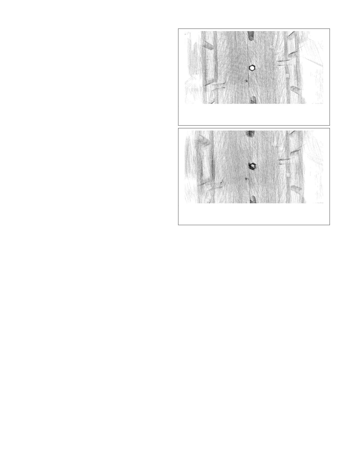
To show the influence of the timestamp offset between la-
ser scanner and motor on the final result, we depict two point
clouds that are obtained using different timestamp offsets.
While all other parameters remain unchanged, the timestamp
offset is set to 24 ms for Figure 9 and to 19 ms for Figure 10.
Both figures show point clouds that originate from the metro
station dataset in top view (cf. Figure 6a).
The greatest difference is recognizable for the pillar in the
center of both figures. While for Figure 9 the pillar is easily
observable in the shape of a hexagon, it is not obvious for
Figure 10. Likewise, the stairs that can be seen on the left and
right side for both point clouds are more distinct for Figure 9.
Thus, it can be stated that the point cloud in Figure 9 indi-
cates a greater clarity. Furthermore, it becomes evident again
that the timestamp offset between laser scanner and motor
has a great effect on the resulting point cloud as an adjust-
ment of merely 5 ms leads to a lower perceived clarity for our
experiments.
Laser Scanner to Camera
Again, both criteria induce similar results for all four datas-
ets, and thus are equally appropriate to use. Nevertheless, we
were not able to find offsets with the same accuracy as for the
laser scanner to motor synchronization which can be observed
by the fact that the plateau of the polynomial in Figure 8a is
much wider than the plateau in Figure 7a. However, since the
images of the camera are only used as an initial guess for the
motion estimation, these results were to be expected. Recall
that the lidar odometry algorithm uses the motion estimate
from the visual odometry to project the laser scan points to
the beginning of the sweep. Afterwards, the lidar odometry
algorithm determines the remaining drift for an entire sweep
that cannot be determined using the visual odometry. This
means, that the lidar odometry algorithm can compensate for
small timestamp offset errors in the optimization step that
is supposed to find the drift for a sweep. The laser scanner’s
measurements, however, are directly linked to both our crite-
ria since an incorrect timestamp offset between laser scanner
and motor leads to erroneously transformed 3D points, which
in turn lead to a worse performance of the
SLAM
algorithm.
Again, the number of iterations needed to find the time-
stamp offset can be reduced by selecting larger intervals for
the determination of data points and fitting a second-degree
polynomial to these data points. For our datasets an interval
of 10 ms between data points is sufficient to obtain similar
results as for an interval of 1 ms.
The results for the timestamp offset between laser scan-
ner and camera range from 59 ms to 140 ms, and thus show a
much wider gap than our results for the laser scanner to mo-
tor synchronization. Additionally, Figure 8 shows that an off-
set of 59 ms (that is optimal for the cemetery dataset in terms
of the average error per match) is far from the optimum for
the metro station dataset and leads to 14 percent less matches
for this dataset. This suggests that we cannot find an optimal
timestamp offset between laser scanner and camera that is
valid for all four datasets, and thus we refrain from specifying
an average over those four datasets. A possible reason might
be the synchronization of the computer’s clocks using
NTP
.
NTP
updates the synchronization parameters between both
Figure 9. Map section generated by the
SLAM
approach for
the metro station dataset using an appropriate timestamp
offset between laser scanner and motor of 24 ms.
Figure 10. Map section generated by the
SLAM
approach for
the metro station dataset using an inappropriate timestamp
offset between laser scanner and motor of 19 ms.
364
June 2018
PHOTOGRAMMETRIC ENGINEERING & REMOTE SENSING


