For the
ZY-3
, during on-orbit operations, geometric calibra-
tion was performed every two to four months on average. Up
to now, more than ten highly accurate geometric calibrations
have been performed around the world. The calibration results
are applied to the satellite ground systems processing the satel-
lite images in the form of a bias compensation matrix and a
CCD
detector look angle file. After on-orbit geometric calibration,
the geometric positioning accuracy of the
ZY-3
imagery without
GCP
s has substantially improved (Jiang
et al.,
2014; Zhang
et al.
2014), and the accuracy of the calibration for camera inner ori-
entation elements was less than 0.25 pixels (Jiang
et al.,
2014),
while the sum of the calibration errors of the on-board instru-
ments installation angles and systematic errors of the attitude
measurements were less than 0.8" (Zhang
et al.,
2014).
High-Precision Attitude and Orbit Postprocessing
The
ZY-3
satellite is equipped with three star trackers and
several gyros. Using a real-time Extended Kalman Filter (
EKF
)
with star tracker and gyro data, on-board attitude data with
measurement accuracies higher than 2.5” (tri-axis, 1
σ
), are ob-
tained for the
ZY-3
satellite ((Xie
et al.,
2013; Tang
et al.,
2015).
Moreover, the
ZY-3
satellite carries a dual-frequency
GPS
re-
ceiver designed primarily for precise orbit determination, with
an accuracy of on-board orbit data exceeding 5 m (1
s
) (Zhao
et
al.,
2013). Attitude and orbit measurements play an important
role in locating objects in satellite images. For
ZY-3
satellites
from a nominal altitude of 505 km, the ground planar location
error and vertical location error caused by 1" attitude error are
approximately 2.5 and 4.5 m, respectively (Tang
et al.,
2015).
And the orbit error directly affects the planar and vertical er-
rors of the images. Therefore, ground-based attitude and orbit
postprocessing is needed to improve the accuracy of the atti-
tude and orbit determination. The ground-based orbit postpro-
cessing uses reduced dynamic orbit determination techniques
based on dual-frequency
GPS
original observations to improve
the orbit determination accuracy and obtain a final accuracy of
0.1 m for the radial, normal, and tangential directions (Zhao
et
al.,
2013). The ground-based attitude post-processing employs
a forward-backward Unscented Kalman Filter (
UKF
) to sup-
press noise using an unscented transformation rather than an
EKF
for a nonlinear attitude system. Using forward-backward
filtering and weighted smoothing with the raw star tracker,
gyro, and
GPS
data, a post-processed attitude with an accuracy
higher than 1.2" (tri-axis, 1
σ
) is obtained (Tang
et al.,
2015).
High-Quality Sensor Calibration Image
The cameras of the
ZY-3
satellite are all formed by several
TDI
CCD
linear arrays, and the images generally need to be stitched
in accordance with the image geometry and radiation character-
istics, before they are used for photogrammetric processing. The
stitching accuracy of the images directly affects the accuracy of
the subsequent photogrammetric production. For example, low
stitching accuracy of Ikonos stereo images will reduce the verti-
cal accuracy (Zhang and Gruen, 2006). Sensor-calibration (
SC
)
images are the most basic image product of the
ZY-3
satellite,
similar to the Level 1A products of the SPOT5 (SPOT Image,
2004), the basic products of the Worldview-2 (Digital Globe,
2010), and the primary products of the Pleiades (De Lussy
et al.,
2005). By constructing an ideal undistorted virtual
CCD
linear
array, resampling based on the ideal virtual
CCD
array model
has been applied to stitch multi
CCD
linear array images in the
productive procedure of
SC
images (Pan
et al.
2013). Mean-
while, the irregular distortion resulting from attitude changes,
discontinuous
CCD
integral time, and imaging system distor-
tions in the satellite raw images are reduced or eliminated, and
projection and intersection errors in image production are neg-
ligible. Thus, the
SC
images from the ideal virtual
CCD
s are ideal
linear central projections without distortion in the vertical orbit
direction, and the integral time of the virtual linear array in the
along-track direction is consistent, without any integral time
jumping (Pan
et al.,
2013; Tang
et al.,
2012). At the same time,
the distortion-free
SC
image enhances its positioning accuracy.
Geometric Positioning Accuracy Estimation Model
After high-accuracy, on-orbit geometric calibration, the errors
of on-board payload and equipments installation, systematic
biases of orbit and attitude measurements, and camera distor-
tion, are largely reduced or eliminated. Based on this premise,
the geometric positioning errors of
ZY-3
imagery are com-
monly determined by the time synchronization error, random
errors of orbit and attitude measurement, and few systematic
errors that are not completely eliminated in the geometric
calibration (Light, 1990). In addition, the calibration errors of
camera inner orientation elements and installation angle for
on-board equipment can also reduce the geometric accuracy
of the satellite images.
Vertical Accuracy Estimation Model
The vertical error caused by the time synchronization error
can be expressed as:
σ
h
r
=
H
B
· d
T
· V
(2)
where
H
is the orbit altitude,
B
is the baseline length,
d
T
is
the time synchronization error, and
V
is the flight speed of
the satellite. In addition, the time synchronization error will
cause orbit and attitude measurement errors. However, given
the high-precision time synchronization accuracy (
≤
20 µs) of
the
ZY-3
, orbit and attitude measurement errors are small and
can be neglected.
The vertical error caused by the image matching error is
given by:
σ
h
M
=
H
B
· d
M
· pixel
(3)
where
d
M
is the image matching error, generally assumed as
0.3 pixels
.
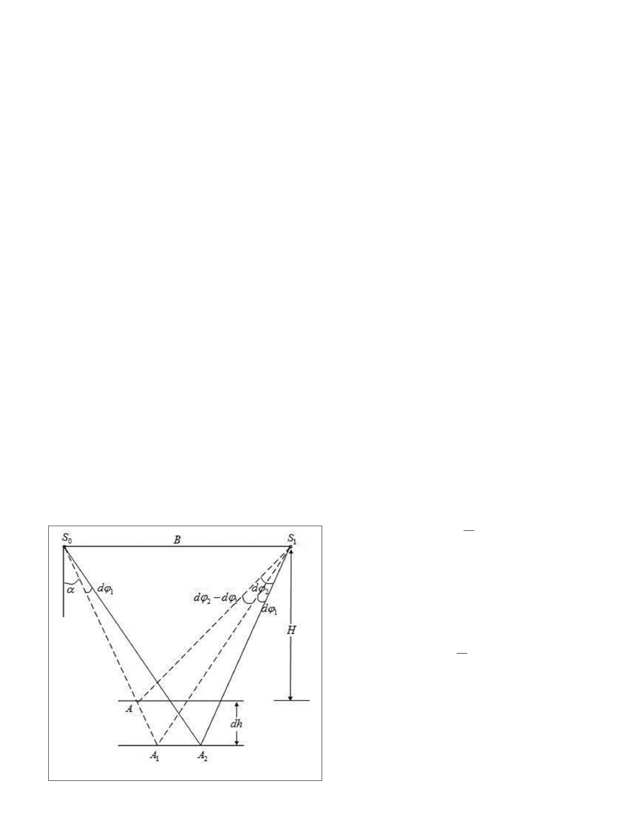
The influence of attitude measurements errors on the verti-
cal accuracy of satellite photogrammetry is observed in the
pitching, rolling, and yawing directions. The rolling angle
errors show only a slight effect on the along-track stereo verti-
cal accuracy and can be considered negligible. Figure 2 shows
the influence on the vertical error of attitude measurements in
the pitch direction.
Since A
1
and A
2
show similar vertical errors, only A
1
can be deduced and the estimation error is unaffected. The
Figure 2. Forward intersection error of the right and left.
PHOTOGRAMMETRIC ENGINEERING & REMOTE SENSING
December 2015
929


