problem is resolved by
OLS
generally, the precondition is that
the coefficient matrix is considered to be error-free, with only
the observation vector having errors. However, the coefficient
matrix includes the coordinates of the feature points, intrinsic
parameter and baseline between binocular cameras. Suppose
that the latter two items are considered pseudo-random obser-
vations; we can conclude that the coefficient matrix contains
errors. Thus, the relative orientation algorithm that integrates
the
WTLS
on the
EIV
model is more rigorous than
OLS
.
Relative Orientation Problem Definition
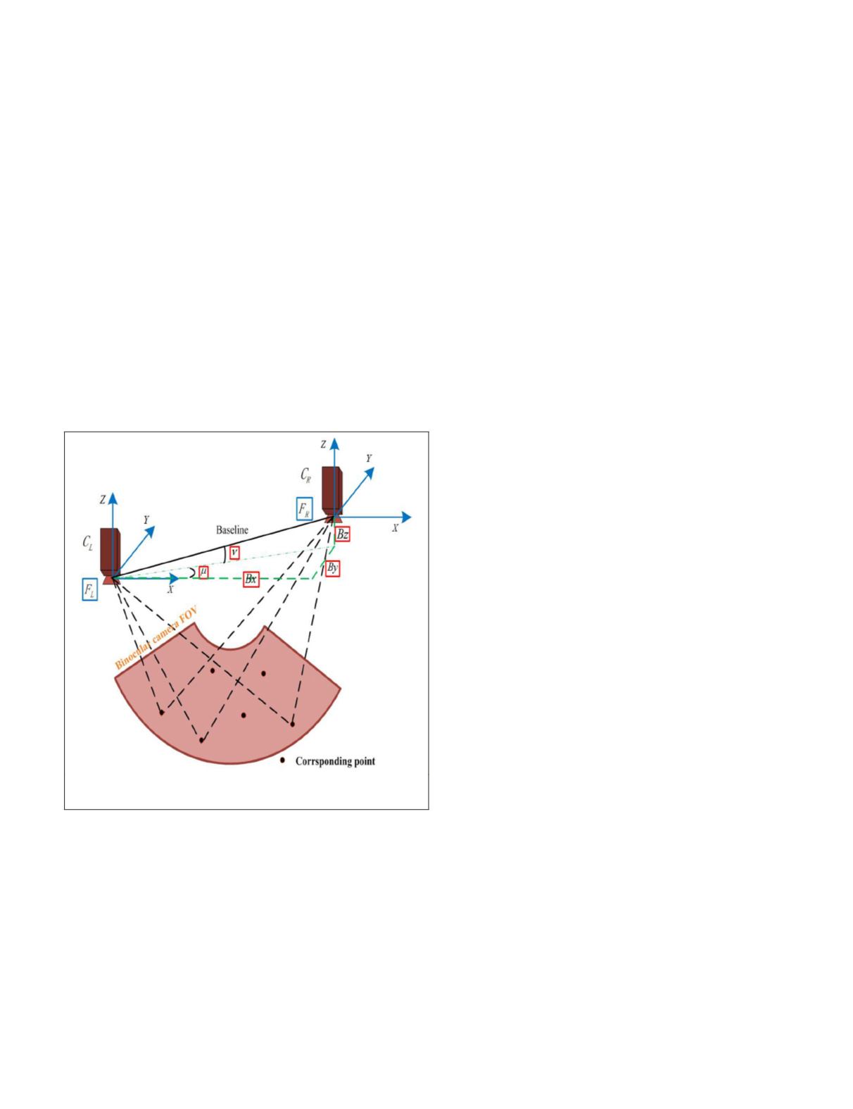
Figure 1 shows an illustration of the epipolar geometry of the
planetary rover’s stereo vision system. It is made up of the
left and right cameras, denoted by (
C
L
,
C
R
). The coordinate
systems of the binocular cameras are denoted as
F
L
and
F
R
,
and view
F
L
is the reference frame. Note that only six pairs
of corresponding points are shown in Figure 1. In theory, the
relative orientation method can work with some (at least 5)
pairs of corresponding points. Although the relative orienta-
tion parameters
can also be defined as parameters external to
the camera, this paper will note definitively that the camera’s
intrinsic parameters remain unchanged during the process
of relative orientation. The initial values of the intrinsic and
extrinsic parameters can be acquired by self-calibration
BA
(Wang, 1990) on the ground before the rover is launched.
Figure 1. Illustration of the epipolar geometry of the
planetary rover’s stereo vision system
Definition 1.
Given a set of pairs of corresponding points, find
the relative orientation parameters between the binocular
cameras.
Camera-External Parameter Estimation
Suppose that the reference frame
F
L
remains unchanged and
the baseline is treated as a unit vector; the relative orienta-
tion parameters will be reduced to baseline components
denoted by
(
B
x
,
B
y
,
B
z
) and Euler angles of exterior orienta-
tion elements denoted by (
φ
0
,
ω
0
,
κ
0
). If the rays from the left
and right camera are intersected, they must lie in a plane that
also contains the baseline. The triple product denoted by the
coplanarity condition (Wang, 1990) is then given:
b
L
R
r
r
'
=
0,
(1)
where
b
= (
B
x
,
B
y
,
B
z
) denotes the vector of the baseline,
r
L
,
r
R
denote the vectors of the ray from the left optical center
and the right optical center to the corresponding points,
R
denotes the rotation matrix containing three independent
elements (
φ
0
,
ω
0
,
κ
0
),
r
′
R
=
r
R
R
.
Each pair of corresponding points will form Equation 1.
Considering that the baseline components (
B
y
,
B
z
) are far less
numerous than baseline
B
, the camera’s external parameters
will become Euler angles (
μ
,
ν
,
φ
0
,
ω
0
,
κ
0
) with
B
y
≈
Bμ
,
B
z
≈
B
ν
, as
shown in Figure 1.
Most research on camera external parameter estimation
gives only Equation 1 for y-parallax, corresponding to the
equation for the y-component of the motion field (Wang,
1990; McGlone,
et al
., 1980). Equation 1 can be viewed as the
following Gauss-Markov model (GMM):
y
=
Ax
–
e~e
N
(
0
,
σ
2
0
Q
),
(2)
where
y
denotes the
n
×1 observation vector of y-parallax,
n
denotes the number of pairs of rays,
A
denotes
an
n
×
m
coefficient matrix with
n
>
m
= rank(
A
)
where
m
= 5
x
denotes
the unknown
m
×1 incremental camera-external
parameter vector (d
μ
, d
ν
, d
φ
0
, d
ω
0
, d
κ
0
),
e
denotes
the unknown normally distributed random error
vector,
σ
2
0
denotes
the unknown variance component,
Q
denotes the
n
×
n
symmetric positive-definite cofactor ma-
trix, and
P
=
Q
–1
denoting the
n
×
n
weight diagonal matrix. The specific
expression of
y
,
A
can be acquired per McGlone,
et al
. (1980).
When the camera-external parameters reach a certain conver-
gence by using
OLS
, the vertical disparity of corresponding
points will be eliminated.
When we consider the errors in the coefficient matrix,
Equation 2 should be further extended to the
EIV
model,
y A E x e
A
= +
(
)
−
(3)
e
vec
N
Q
Q
m
e
E
I
A
A
=
( )
~
,
0
0
0
0
0
2
σ
7
,
where
E
A
denotes the
n
×
m
matrix of added random errors in the
coefficient matrix
A
,
e
A
= vec(
E
A
) denotes
the same in
nm
×1
vector form,
vec
(·) denotes
the operator that stacks one column of a matrix
underneath the previous one,
7
denotes Kronecker–Zehfuss product of matrices, defined
as
G
7
H
: = [
g
ij
·
H
]
if
G
= [
g
ij
], and
I
m
denotes
the
m
×
m
identity matrix.
When the camera-external parameters with small range
changes can be obtained before the launch, it is noted that
the camera-external parameters can also be viewed as ficti-
tious observations. In this case, Equation 2 should be supple-
mented by some fictitious observation equations to improve
robustness:
PHOTOGRAMMETRIC ENGINEERING & REMOTE SENSING
October 2018
607


