X, Y, Z coordinates in the planetary rover’s body coordinate
system
F
r
should be at least as large for our method to acquire
high-precision pose estimation. According to some pairs of tie
points at the adjacent two stations, the test content includes
the proposed algorithm where the weight diagonal matrix
W
is the
identity matrix (named
TLS
), and
W
is from Equa-
tion 23 (named
WTLS
). The
WTLS
algorithm is then compared
with the
BA
method based on the ordinary
LS
(named
BA
+
LS
)
(Alexander,
et al
., 2006; Di,
et al
., 2008), parallaxBA (Zhao,
et
al
., 2015), and
LM
(named
BA
+
LM
) algorithms (Li,
et al
., 2016).
In the
BA
+
LS
, parallaxBA and
BA
+
LM
algorithms, the initial
parameters of camera poses can be provided by the
WTLS
algo-
rithm. It is important to note that during the selection process,
the tie points should be evenly distributed in the overlapping
areas between the stereo
FOV
in previous and current stations.
If one tie point is perfectly multicollinear or coplanar with
the adjacent tie points, then
WTLS
and other
BA
algorithms
cannot obtain the high-precision pose estimation of the rover
and may even fail.
The C/C±± source code of parallaxBA is available on
OpenSLAM
/
). The open source code
of the
LM
(named
BA±LM
) algorithm is available in the
BA
packages SBA (
.
html#download
). In the process, the (non-negative) damping
factor is adjusted at each iteration. When the damping factor
is set to zero, the SBA algorithm will be reduced to
BA±LS
. It
is important to note that the SBA code should be compiled by
CMake on Windows
®
systems.
The distribution of the selected tie points can be viewed in
Figure 7, and the results are all listed in Table 8.
It is noted that the variance component
σ
2
0
in the proposed
WTLS
and the
BA
algorithms are different, which respectively
indicate the mean square errors (MSEs) of the reprojections
and the rover poses. When the camera pose estimation has
been given by the
BA
algorithms, we can easily acquire the
rover poses by the coordinate system transformation frame-
work, which indicates the translation parameters (
Δ
X
,
Δ
Y
,
Δ
Z
,
φ
,
ω
,
κ
) between the reference frame
F
L
and the planetary
rover’s body coordinate system
F
r
.
From the ninth row in Table 8,
BA
+
LS
converges to 1.44
in 10 iterations, parallaxBA converges to 1.40 in 7 iterations,
and
BA
+
LM
converges to 1.43 in 16 iterations. The above three
algorithms stop because the maximum number of iterations
(100) is reached (the
MSE
value will change very little if the
Figure 6. Stereo-matching image points of the CE-3 lunar
rover’s images. The white crosses “+” represent the
matching image points, which lie at the top and center area
of the images.
Table 6. The external parameters of the lunar rover’s stereo
vision system.
OLS
TLS
WTLS Truth data
μ
(°)
-2.02
-0.56
-0.49
-0.13
ν
(°)
1.93
-0.50
-0.56
-0.95
φ
0
(°)
-0.23
-0.35
-0.33
-0.31
ω
0
(°)
0.92
-0.06
-0.02
0.45
κ
0
(°)
1.13
1.00
0.89
0.02
σ
0
(mm)
0.081
0.027
0.024
-
Table 7. Residual of the coefficient matrix
A
and observation
vector(
y
(
* 10
–3
).
-0.006 0.010 -0.012 0.004 -0.001 -0.314
-0.001 -0.004 0.001 -0.001 -0.002 -0.145
0.009 0.012 0.002 0.001 0.002 0.263
-0.003 -0.025 -0.002 -0.001 -0.001 -0.201
-0.005 0.006 -0.005 0.000 0.002 -0.102
0.007 -0.012 0.002 -0.001 -0.001 0.207
-0.008 0.017 -0.003 -0.002 -0.001 0.399
-0.003 -0.047 -0.007 -0.004 -0.002 -0.781
-0.012 0.017 0.002 0.003 -0.002 0.569
0.002 -0.021 0.001 -0.002 0.001 -0.422
-0.004 0.012 0.002 0.010 0.003 0.605
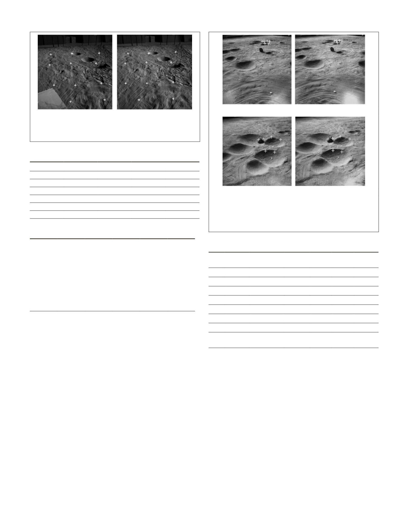
(a) (b)
(c) (d)
Figure 7. Tie points of stereo images at the adjacent two
stations in the test field: (a), (b) Images of the lunar rover
taken at the previous station S1; and (c), (d) Images of the
lunar rover taken at the current station S2, with the white
crosses as the tie points
Table 8. The lunar rover pose results using the different
algorithms in station S2.
BA+LS parallaxBA BA+LM TLS WTLS
Truth
data
Δ
(m)
4.207
4.199
4.208 4.090 4.088 4.145
Δ
(m) -4.782
-4.780
-4.782 -4.753 -4.699 -4.470
Δ
(m)
0.230
0.233
0.231 0.213 0.234 0.312
ρ
-
-
-
1.043 1.035
-
φ
(°)
-5.30
-5.20
-5.26 -4.44 -4.58 -0.31
ω
(°)
1.79
1.76
1.82 1.70 3.19 2.80
κ
(°)
82.11
82.32
82.11 81.90 82.40 83.90
σ
0
1.44
(pixel)
1.40
(pixel)
1.43
(pixel)
3.4
(mm)
3.1
(mm)
-
PHOTOGRAMMETRIC ENGINEERING & REMOTE SENSING
October 2018
613


