indoor GPS (
IGPS
), whose measurement accuracy is 1.0
″
and
whose coordinate measurement accuracy is 0.1 mm. Through
the common control points, the numeric conversion pa-
rameters between
F
C
and
F
IGPS
can be obtained. Immediately
following, the numeric conversion parameters between
F
r
and
F
IGP
can also be obtained through the common feature points.
When the 3D coordinates of the feature points are measured
using
IGPS
, the numeric conversion parameters between
F
C
and
F
r
can be calculated immediately, which will be viewed
as the truth data of the rover pose (the seventh column in
Table 7; the third and fourth columns in Table 8).
Using binocular cameras to acquire images is a common
method of the rover’s stereo vision system. The intrinsic and
extrinsic parameters of the single camera can then be acquired
by using the self-calibration bundle adjustment model with
control points. In this paper, it is assumed that the intrinsic
parameters are constant: the extrinsic parameters of the left
camera and right camera are denoted by (
R
1
,
t
1
) and (
R
2
,
t
2
)
in control reference frame
F
C
. The relative orientation pa-
rameters (
R
,
t
) can be obtained by the equation
t
=
R
2
–1
(
t
1
–
t
2
),
R
=
R
2
–1
R
1
, which can also be viewed as the truth data of the
epipolar geometry of the binocular cameras (the fifth column
of Table 2). The intrinsic parameters of the navigation cam-
eras are listed in Table 1.
Table 1. The intrinsic parameters of the CE-3 lunar rover’s
navigation cameras.
camera
f
(pixel)
x
0
,
y
0
(pixel)
radial
distortion
tangential
distortion
k
1
k
2
p
1
p
2
Left 1181.4 3.1,11.5
-2.1597
×10
-8
3.1118
×10
-14
1.4603
×10
-7
-3.1304
×10
-7
Right 1196.6 -1.0, -18.4
-2.2209
×10
-8
3.0968
×10
-14
-5.3254
×10
-9
-2.8598
×10
-7
In Table 1, The intrinsic parameters including the focal
length
f
, principal point (
x
0
,
y
0
), and lens distortion (
k
1
,
k
2
,
p
1
,
p
2
) can be seen in the equation ,
∆
x
=(
x
–
x
0
)(
k
1
r
2
+
k
2
r
4
) +
p
1
(
r
2
+2(
x
–
x
0
)
2
) +2
p
2
(
x
–
x
0
)(
y
–
y
0
),
∆
y
=(
y
–
y
0
)(
k
1
r
2
+
k
2
r
4
) +
p
2
(
r
2
+2(
y
–
y
0
)
2
) +2
p
1
(
x
–
x
0
)(
y
–
y
0
), where
∆
x
,
∆
y
, represent the calibration
correction of the image coordinates due to the system error
from lens distortion (Wang, 1990; McGlone,
et al
., 1980).
Estimation results of the epipolar geometry of the binocular cameras
In this section, six pairs of image points with uniform distri-
butions are selected by the
SURF
algorithm (Figure 4). We set
the variance
σ
2
p
as 1/3 and the initial weight matrix
P
as the
identical matrix. Because the estimated value of the unknown
variance component ˆ
σ
2
p
is calculated in real time during itera-
tion, the weight coefficients (the diagonal elements of weight
matrix
P
) should be set as
k
(ˆ
σ
2
p
/
σ
2
p
). According to prior knowl-
edge of image resolution, the weight matrix
P
can be set as
(ˆ
σ
2
p
/
σ
2
p
)
diag
(1 1 1 0.1 0.1 0.1) from the top down. To simulate
variations of the camera-external parameters, the true values
of the camera-external parameters are added by the standard
deviation (–0.45, 0.60 0.10 – 0.60 1.0) degree. The modified
values of the camera-external parameters will then be viewed
as fictitious observations with equal precision.
When the relative orientation algorithms based on
TLS
(
P
is
identity) and
WTLS
(
P
= (ˆ
σ
2
p
/
σ
2
p
)
diag
(1 1 1 0.1 0.1 0.1)) are com-
pared with
OLS
(Stewenius,
et al.
, 2006), the result is listed in
Table 2. The baseline length is 269.2 mm.
From the second column and the third column in Table 2,
the camera-external parameters (
u, v,
φ
0
,
ω
0
,
κ
0
) based on
TLS
are much closer to the true data than are those of conventional
OLS
. Through the seventh row, the errors
σ
0
based on
OLS
and
TLS
are 0.107 mm and 0.034 mm, respectively, which indicate
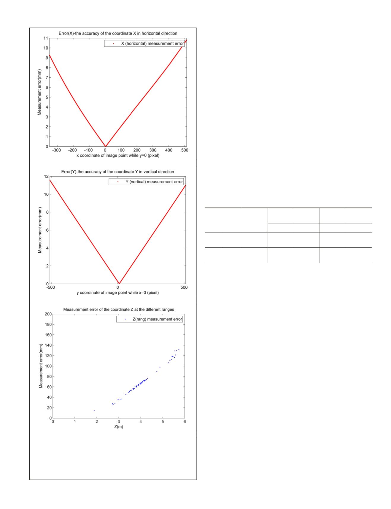
(a)
(b)
(c)
Figure 3. Accuracies of the coordinates
X,Y,Z
of CE-3
lunar rover’s stereo vision system: (a)
σ
X
: the accuracy of
coordinate
X
in the horizontal direction (
y
= 0); (b)
σ
Y
: the
accuracy of coordinate
Y
in the vertical direction (
x
= 0);
and (c)
σ
Z
: the accuracy of coordinate
Z
in the opposite
direction of the optical axis.
PHOTOGRAMMETRIC ENGINEERING & REMOTE SENSING
October 2018
611


