parallaxBA is better than
BA±LS
and
BA±LM
in both theory
(Zhao,
et al
., 2015) and practice ( so we compare only
WTLS
with parallaxBA. During the move from the “N0203” station
to the “N0204” station, the wheels of the rover skid. Hence,
the moving path (red line) shows the sudden change. In all
such cases, e.g., slope, wheel slippage and sinkage, the initial
values of the camera pose from the odometry are insufficient-
ly accurate. Of course, the parallaxBA method works well
when the initial values of the camera pose are obtained from
the forward intersection process in the “N0203” station and
space resection several times in the “N0204” station. If the
initial values of the camera pose are obtained only from the
odometry data, the
BA±LS
, parallaxBA and
BA±LM
algorithms
fail. In order to reduce error accumulation caused by wheel
slippage and
IMU
drift in dead reckoning, cross-site visual
localization and
DOM
matching localization methods are
developed to localize the rover at way points and the overall
traveled distance from the Chang’E-3 lunar rover is 114.8
m from cross-site visual localization and 111.2 m from
DOM
matching localization (Liu,
et al.
, 2015). However, the
DOM
matching localization method depends upon the resolution of
the Local DEM or
DOM
and the accuracy of image registration.
When the rover travels short distances, the
BA
algorithms and
WTLS
have more accurate localization results than the
DOM
matching localization method.
The rover’s coordinate system transformation framework
includes the pitch, yaw angle of the cradle and the angle of
each joint of the stereo camera system, and the angle measure-
ment accuracy is 0.3°. The mean absolute localization accura-
cy of the feature points in the rover’s coordinate system trans-
formation framework is 45.4mm at the range (0.5m~5.9m).
However, the mean absolute localization accuracy without the
rover’s coordinate system transformation framework is 6.6mm
at the range (0.5m~5.9m). Thus, the angle measurement error
is non-negligible.
Because the camera poses and the rover poses have com-
plicated non-linear relations in the rover’s coordinate system
transformation framework, the angle measurement error could
not be cancelled out through forward and backward transfor-
mations. Due to the existing measurement errors in the trans-
formation framework, the precision of the 3D coordinates of
the tie points by forward intersection is much lower than the
case without the transformation framework, which affects
the rover’s visual pose estimation by
WTLS
or
BA
. To avoid the
measurement errors, the next section will give the experimen-
tal results.
Experimental Results of the Simulated Stereo Camera System’s Visual
Localization in the Outdoor Test Field
It is common knowledge that the desert in Dunhuang city,
which is the test site of the China’s first lunar rover (Yutu), is
very similar to the Martian and lunar surfaces. In the course
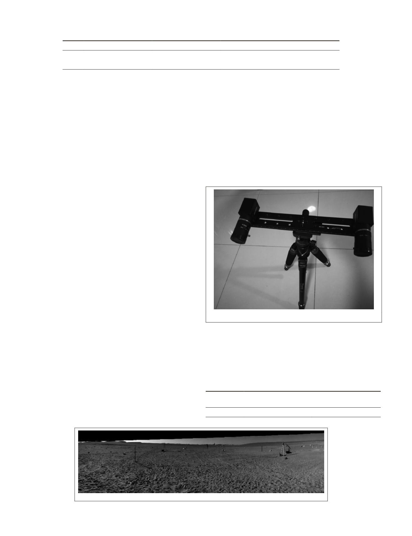
of the experiment, one simple stereo camera system is used
to simulate the rover’s camera system, as shown in Figure
9. Indoor GPS (
IGPS
) is required, as shown in Figure 10. The
reference frame
F
r
in a previous section will be replaced with
the reference frame
F
ccr
of the corner cube reflector. The cor-
ner cube reflector is installed on the stabilization platform of
the stereo camera system. When the simulated stereo camera
system moves, the rigid translation
R
and rotation
t
between
F
ccr
and
F
C
can be calculated immediately, which can be
viewed as the true data of the simulated stereo camera system
pose. In this case, the errors in the coordinate system transfor-
mation framework of the lunar rover can be avoided, and the
experimental result can reflect the precise location of
WTLS
and
BA
more accurately.
Figure 9. The simulated stereo camera system
In Figure 10, twenty pairs of stereo images are used to gen-
erate the panoramic image.
The intrinsic parameters of the simulated stereo camera
system are given in Table 12.
The extrinsic parameters by the proposed relative orienta-
tion method are as follows in Table 13:
Table 13. The extrinsic parameters of the simulated stereo
camera system.
Stereo camera
Translation
vector (mm)
Rotation
vector (rad)
253.5 -1.3 -3.4
0.00076 -0.00380 -0.00341
Figure 10. The panoramic image of a certain station
Table 12. The intrinsic parameters of the simulated stereo camera system from the MATLAB camera calibration toolbox .
camera Focal Length (pixel)
Principal point (pixel)
Distortion:
k
1
k
2
k
3
p
1
p
2
p
3
Left
4770.7, 4768.2
1244.6, 1095.7
-0.09282 1.29345 -0.00063 -0.00122 0.00000
Right
4770.0, 4769.1
1188.9, 987.9
-0.05804 0.39702 -0.00097 -0.00308 0.00000
616
October 2018
PHOTOGRAMMETRIC ENGINEERING & REMOTE SENSING


