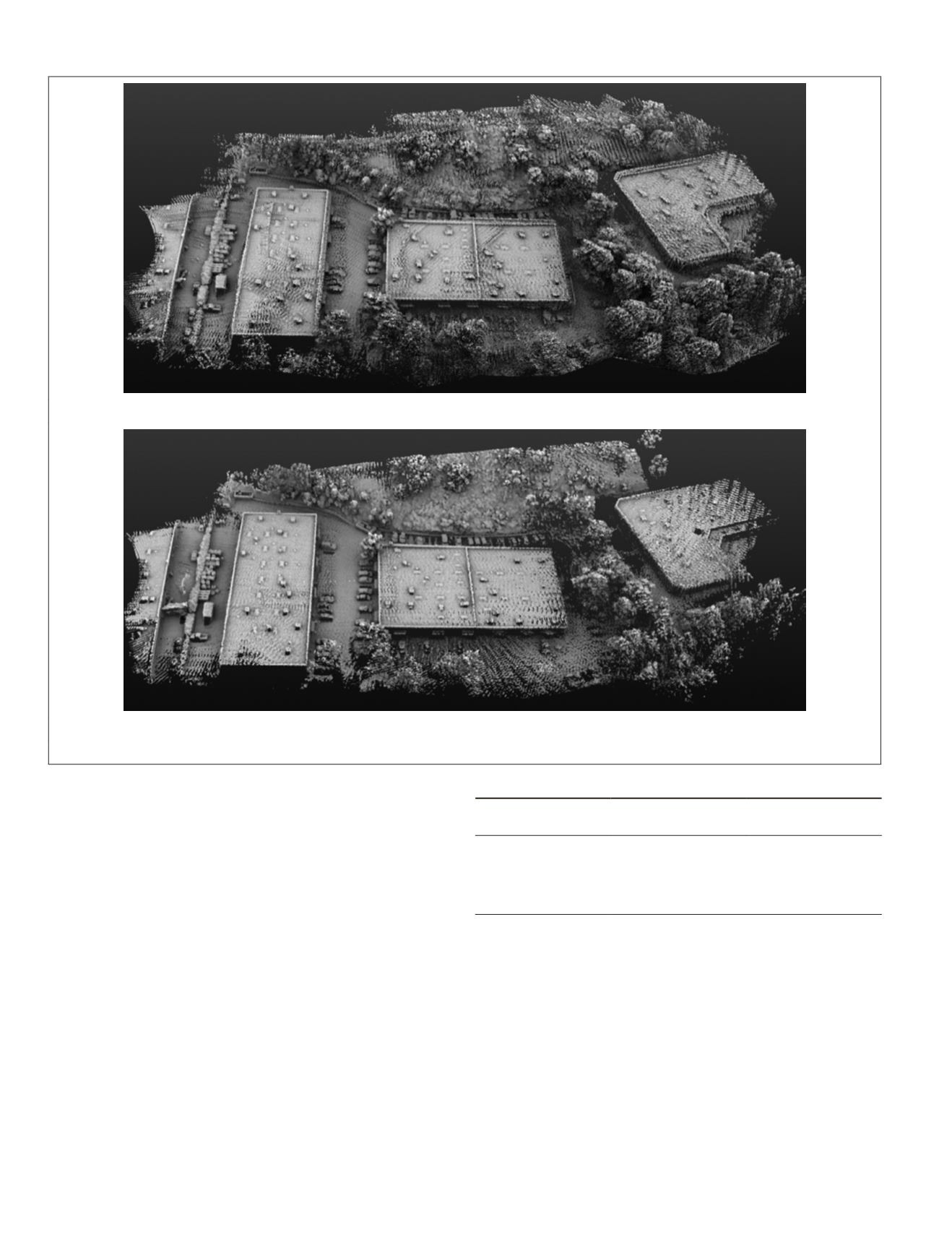
obtained with the presented approach. As it can be seen from
Figure 12 a, the point cloud generated with non-calibrated
parameters are not aligned properly on different cross paths.
In order to evaluate the impact of the calibrated boresight
parameters on the geo-referenced point clouds, the
RMS
error
values of the
GCP
in the area were measured. Table 2 summa-
rizes the accuracy assessment on the
GCPs
. Once the boresight
value determined from proposed approach is used, the point
clouds are all aligned properly within the system specifica-
tion, i.e.,
RMS
of ±5 cm.
Discussion and Conclusions
The recent, low-cost, small, and light-weight lidar sensors
offer clear advantages for
MMS
applications. However, they
pose calibration challenges due to their low point densities
along with their need to be calibrated frequently to accom-
modate new applications. Additionally, the custom-built
MMS
,
such as
UAV
payloads typically require frequent boresight
calibration due to inherent instability of the mounted sen-
sors that may be installed and removed from the
UAV
for each
mission. As incorrect boresight parameters directly impact
the accuracy of georeferenced lidar, they must be determined
with higher confidence. To this end, the authors developed a
laboratory calibration method that determines the boresight
misalignment while avoiding the other factors that affect
the accuracy of lidar point cloud. The presented calibration
method uses plane-to-plane correspondence that overcomes
the challenges associated with point based or point-to-plane
methods especially for low-density lidar systems. The experi-
ments demonstrate that the unknown boresight calibration
values can be computed by minimizing the volume formed
between lidar and control surfaces. In a man-made environ-
ment, there are abundant planar features available, hence this
method is feasible. As this method does not look for point-to
point or point-to-plane correspondence, it is feasible even
with low density lidar point cloud generated by low-cost and
light weight sensors. This method can be expanded to use
free-form surfaces instead of planes in both control and lidar
Table 3. Boresight calibration and Accuracy Assessment on
GCP
.
GCP ID
RMS (3D)
Uncalibrated [m]
RMS (3D)
Calibrated [m]
1
0.26
0.04
2
0.54
0.05
3
0.43
0.04
4
0.78
0.03
5
0.65
0.05
(a)
(b)
Figure 12. Point Cloud Registration using uncalibrated boresight (a) versus calibrated boresight parameters (b).
626
October 2018
PHOTOGRAMMETRIC ENGINEERING & REMOTE SENSING


