the
RP
n
P
is also close to the non-linear method. However, the
RP
n
P
is slightly worse for the translation recovery.
Real Data
In this section, we investigate the relative performance of
the different
SPR
solutions (i.e., the proposed approaches as
well as the non-linear and
RP
n
P
) when dealing with real data,
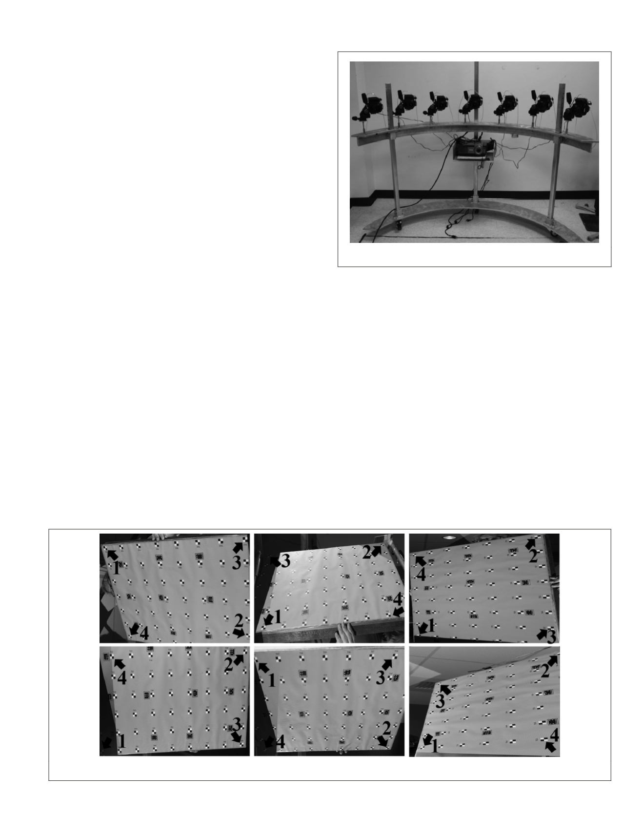
which is a calibration dataset of the multi-camera system in
Figure 5. This real dataset contains 118 images captured from
seven cameras, focusing on a 100 × 80 cm planar test field.
The object points are a grid of 7 × 9 targets printed to scale
from a
CAD
model and pasted onto a planar board. Considering
the test field as the XY plane of the object coordinate system
and one of the targets as the origin, the planar coordinates
of other targets are assigned. The planar coordinates of the
targets are assumed to be highly accurate as they are printed
to scale using a well-calibrated printer and their Z coordinates
are assumed to be zero. These assumptions are verified after
executing a bundle adjustment that estimates accurate
EOP
s of
the captured images,
IOP
s of the utilized cameras, as well as
targets’ coordinates. The
RMSE
of the targets’ coordinates after
bundle adjustment when compared to the
CAD
-based coordi-
nates, which were used as an input to the printer, turned out
to be ±20 microns and the standard deviation of the target’s Z
coordinates after the bundle adjustment procedure is in the
range of ±2 mm. The corresponding image points are extracted
automatically from the images with sub-pixel accuracy. In
order to estimate the
EOP
s, a self-calibrating bundle adjustment
is executed on the real dataset by considering the principal
point coordinates and principal distances (
IOP
s), and radial
lens distortions in the collinearity equations. The position and
orientation of the bundle adjustment datum are defined by
using the following minimum constraints: fixing XYZ of one
corner target in the test field, XY of the opposite corner target,
and Z value of a third corner target. The datum scale is fixed
using three distance constraints between some of the test field
targets. The convergent camera poses during the data collec-
tion constitute strong photogrammetric network and the self-
calibrating bundle adjustment converges to a small a-posterio-
ri variance factor (with a square root less than half a pixel size)
which indicates highly accurate estimation of
EOP
s (bundle-
based
EOP
s). The translation parameters of the bundle-based
EOP
s are in the range of approximately ±110 cm and the image
attitudes vary from very oblique to almost vertical (
ω
and
φ
rotation angles vary between ±75° and ±65°, respectively, and
the
κ
rotation angles changes between –20° and +130°). Figure
6 shows some of the images used in the real dataset as well
as the points which are used later as the minimal data for the
SPR
methods (points 1, 2, and 3 are used for the non-linear and
quaternion-based general methods while points 1, 2, 3, and 4
have been used for the projective and
RP
n
P
methods). Differ-
ent poses of the test field relative to the cameras strengthen
the geometric network of the bundle adjustment and provide
diverse
EOP
s, to be recovered by the investigated
SPR
methods.
In this experiment, each
SPR
method is tested for three,
four, and all visible points in each image (varing from 23 to 63
points). For each test, the
RMSE
of the differences between the
bundle-based
EOP
s and estimated
EOP
s for all the images are
computed. Figure 7 depicts the
RMSE
of the differences for the
rotation angles and translation components. The results show
that the accuracy of the quaternion-based general approach
is close to the non-linear method for both the rotation and
translation parameters with minimal data (Figure 7a). Al-
though the
RP
n
P
works quite well with four points (Figure 7b),
but performs less accurate than the quaternion-based general
approach using all points, especially for the rotation recovery
(Figure 7c). The projective approach performs poorly using
Figure 6. Six out of the 118 images used in the real dataset and the three/four targets used as minimal data.
Figure 5. The multi-camera data acquisition system.
PHOTOGRAMMETRIC ENGINEERING & REMOTE SENSING
March 2015
215


