The 3
D
coordinates of the target centers were measured using
a total station, with a standard deviation below 1 mm. The
3
D
coordinates were recorded in a local coordinate system.
A stereo pair of images was taken and the image coordinates
of the targets were measured. The image coordinates and 3
D
coordinates of the targets were used to calculate the 3
D
coordi-
nates of the two cameras’ principle points in the local coor-
dinate system based on Equations 1 and 2. At the meantime,
the 3
D
coordinates of the two cameras’ principle points in the
local reference frame of the dual camera system were ob-
tained (refer to Figure 1). A transformation equation was then
formulated based on the 3
D
coordinates of the two cameras’
principle points in the local coordinate system and in the
local reference frame. The measured 3
D
coordinates of all the
targets were then transformed into the local reference frame of
the dual camera system based on the transformation equation.
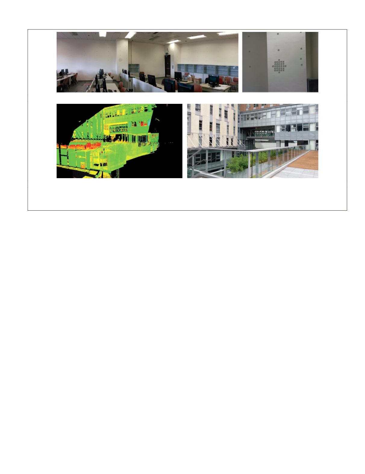
The outdoor experimental environment is shown in Plate
2c and 2d. The distance from the camera system to the middle
of the experimental area (the footbridge in Plate 2c) is ap-
proximately 40 m. The lidar point cloud of the experimental
area was obtained to provide control and check data in the
experiment. The lidar point cloud was collected using a Leica
ScanStation HDS3000.
The 3
D
coordinates of the point cloud data were recorded
in a local coordinate system which was then transformed
to the local reference frame of the dual camera system. The
root-mean-square error (
RMSE
) was found by comparing the
measurements using a steel tape with measurements using the
lidar point cloud data. The
RMSE
found was 4.6 mm, indicat-
ing that the point cloud was highly precise.
The experiments were carried out in the following steps:
1. For both indoor and outdoor experiments, stereo im-
ages were taken by both cameras simultaneously, using
a specific baseline length, and specific
PTZ
focal length
and pan angle.
2. The image coordinates of control points on the stereo
images were measured. For the indoor experiment, the
image coordinates of the targets used as control points
were measured. For the outdoor experiment, at least
eight feature points evenly distributed in the image
were manually identified and measured for each im-
age pair, and their corresponding 3
D
coordinates were
derived from the lidar point cloud.
3. The control points were then used to calculate the
orientation parameters of the two cameras, using Equa-
tions 1 and 2.
4. For each stereo pair, a feature point near the center of
the image acquired by the
PTZ
camera was selected and
used as a checkpoint. The 3
D
coordinates of the check-
point were calculated through space intersection, using
Equations 1 and 2.
5. The ground truth of the checkpoint was obtained. For
the indoor experiment, the 3
D
coordinates of the check-
point were interpolated from four nearby target points
with known coordinates using bi-linear interpolation.
For the outdoor experiment, the 3
D
coordinates of the
checkpoint were derived from the lidar point cloud by
referring to the feature point on the images.
6. The 3
D
coordinates of the checkpoint were calculated
from the geometric model in Step 4 and its ground
truth was determined from Step 5. The measurement
error was the difference between these two results.
7. The baseline length, focal length of the
PTZ
camera, and
pan angle of the
PTZ
camera were altered to correspond
to the three scenarios in the theoretical analysis and
Monte Carlo simulation, and Steps 1 through 6 were
repeated.
8. The experimental results were summarized and analyzed.
In the actual experiments, a rigid base was used to mount
the two cameras, which was made of stainless steel plate and
manufactured by a precision machining instrument. There
are graduations from 0.5 m to 1 m on the rigid base for setting
up the baseline lengths in the experiments, and the exact
(a) (b)
(c) (d)
Plate 2. The indoor and outdoor experimental environments: (a) The indoor facility with targets mounted on the two walls, (b) a zoomed-
in view of the targets in the indoor facility, (c) the outdoor experimental environment, and (d) the LiDAR point cloud of the outdoor
experimental area.
PHOTOGRAMMETRIC ENGINEERING & REMOTE SENSING
March 2015
225


