where (
x
s
, y
s
),
f
l
, and
s
l
represent the principal point, focal
length, and skew of the surveillance camera, respectively. If
point correspondence (Zhu
et al
., 2007; Wu
et al
., 2011) is
identified on the images acquired by the
PTZ
and surveillance
cameras; its 3
D
coordinates in the local reference frame can be
determined from Equations 1 and 2.
The interior orientation parameters (
IOP
s) of the surveil-
lance camera, (
x
s
, y
s
),
f
l
, and
s
l
, were calibrated using tradi-
tional calibration methods (Tsai, 1987), whereas the
IOP
s of
the
PTZ
camera, (
x
z
, y
z
),
f
r
, and
s
r
, were subject to changes
in zoom value. Calibration of the zoom lens was performed
independently at a few lens settings covering the entire zoom
span, and the calibrated results were subsequently modeled
using polynomials. We developed an innovative and flexible
zoom-lens calibration method (Wu
et al
., 2013) and used it to
calibrate and model the
PTZ
camera.
The parameters of the surveillance camera and the
PTZ
camera are listed in Table 1. They were used as references in
the following theoretical analysis, Monte-Carlo simulation,
and experimental analysis.
T
able
1. C
amera
P
arameters
Surveillance camera
PTZ camera
Focal length
8 mm
10-120 mm
FOV
80°
5°–30°
Image size
2560 × 900 pixels
1280 × 1024 pixels
Pixel size
2.5 µm
5.3 µm
Pose control
Fixed
±45° pan, ±30° tilt
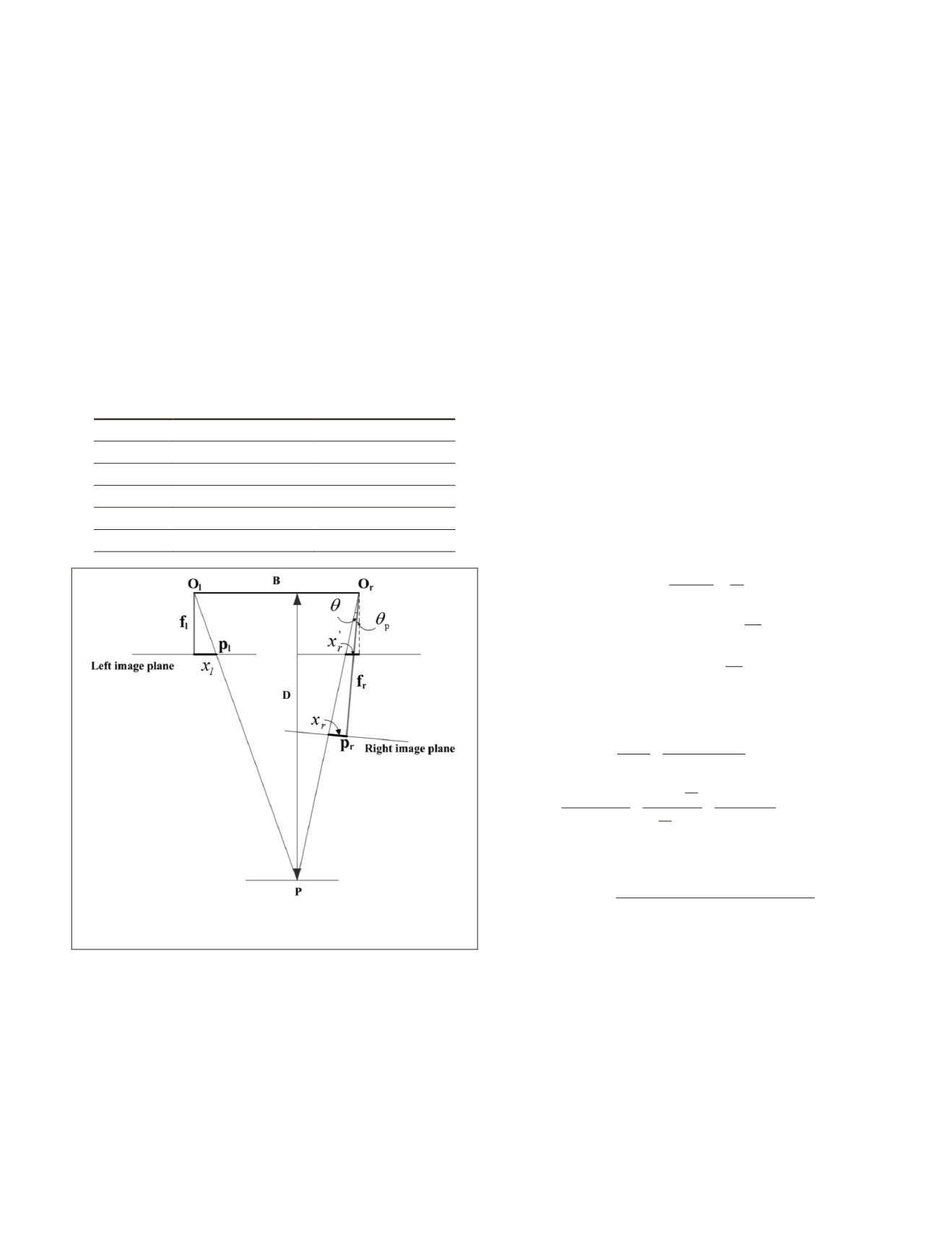
Figure 2. Illustration of the geometric principle of the asymmet-
ric stereo configuration.
Theoretical Accuracy Analysis
The proposed dual camera system with an asymmetric photo-
grammetric configuration is capable of producing a stereo pair
of images for which the focal lengths of the two cameras are
different and in which the two camera axes are not parallel to
each other or perpendicular to the baseline, which presents
novel problems that are not found in normal symmetrical
configurations. We carried out a theoretical analysis of the
measurement capability of the proposed dual camera system
under different baseline lengths, different focal lengths and
different pan angles of the
PTZ
camera.
As measurement error in the range direction is always
larger than in the other two directions (Di and Li, 2007), we
have used range error to represent measurement accuracy in
the following discussions. Figure 2 illustrates the geometric
principle of the asymmetric photogrammetric configuration.
We assumed that the surveillance camera in the left was fixed
and that its camera axis was perpendicular to the baseline. Its
focal length
f
l
was fixed. The
PTZ
camera in the right had vary-
ing focal length
f
r
, and its pan angle
θ
P
and tilt angle
θ
T
varied.
According to the geometric principle illustrated in Figure 2,
only the pan angle
θ
P
needs to be considered when investigat-
ing the measurement accuracy in the range direction.
B
is the
baseline length between the two camera projective centers.
For a point
P
in the object space, its imaging points in the
left image and right image are
p
l
and
p
r
. Their image coor-
dinates along the
x
direction are
x
l
and
x
r
, respectively.
D
is
the distance or range from the object at point
P
to the base-
line;
θ
is the angle between the ray from object point
P
to the
perspective center of the
PTZ
camera
O
r
, and the optical axes
of the
PTZ
camera. For the convenience of geometric relation-
ship derivation, the positive or negative signs of
θ
P
and
θ
are
defined as follows:
θ
P
will have positive values when the
optical axis of the
PTZ
camera rotates towards the surveillance
camera, and negative values in the opposite case.
θ
will have
negative values when the ray rotates clockwise with respect
to the optical axis of the
PTZ
camera, and positive values in
the opposite case. For the case illustrated in Figure 2,
θ
P
is
positive, and
θ
is negative.
From Figure 2, the following equations can be derived
based on the geometric relationship:
x x
B
f
D
tan
x
f
tan
x
f
l
r
l
p
r
l
r
r
−
=
−
(
)
= −
( )
=
'
'
θ θ
θ
(3)
From the above equation the range
D
can be
calculated by:
D
=
−
=
+
−
(
)
f B
x x
f B
x f
l
l
r
l
l
l
p
'
tan
θ θ
, while
tan
tan tan
tan tan
tan
tan
ta
θ θ
θ
θ
θ θ
θ
θ
p
p
p
p
r
r
r
r
p
r
x
f
x
f
f
−
(
)
=
−
+
=
−
+
=
1
1
n
tan
θ
θ
p r
r
r
p
x
f x
−
+
. By combining
these two equations the following can be obtained:
D
f B f x tan
x f x f
f f x x tan
l
r
r
p
l r
r l
l r
r l
p
=
+
( )
− + +
(
)
( )
θ
θ
(4)
From the above equation, it can be seen that the measurement
accuracy depended on the image coordinates
x
l
and
x
r
(their
influences together being similar to parallax in the normal
symmetric stereo case), the baseline length
B
, the focal length
f
r
of the
PZT
camera, and the pan angle
θ
P
of the
PZT
camera.
The focal length
f
l
of the surveillance camera was fixed in the
proposed dual camera system; therefore, it is a constant in
the above equation. We investigated the influence of baseline
length
B
on the measurement accuracy. Since the two cam-
eras were rigidly mounted on the base when adjusting the
baseline; therefore, the error propagation of baseline length
B
itself is ignored in the following error-propagation derivation.
Through error-propagation derivation based on Equation 4,
PHOTOGRAMMETRIC ENGINEERING & REMOTE SENSING
March 2015
221


