dual camera system. Then, we describe the geometric modeling
of the asymmetric photogrammetric configuration, and pres-
ent the theoretical accuracy analysis and error propagation of
such a configuration with respect to intra-camera baseline,
PTZ
camera focal length, and
PTZ
camera pan angle. Then, a Monte
Carlo simulation was carried out to investigate the attainable
accuracies of the asymmetric photogrammetric configuration
under the same conditions. After that, actual experimental
analyses in indoor and outdoor environments were conducted
to verify the theoretical and simulated analysis results. Finally,
we present a discussion and our concluding remarks.
A Dual Camera System with Asymmetric Photogrammetric
Configuration
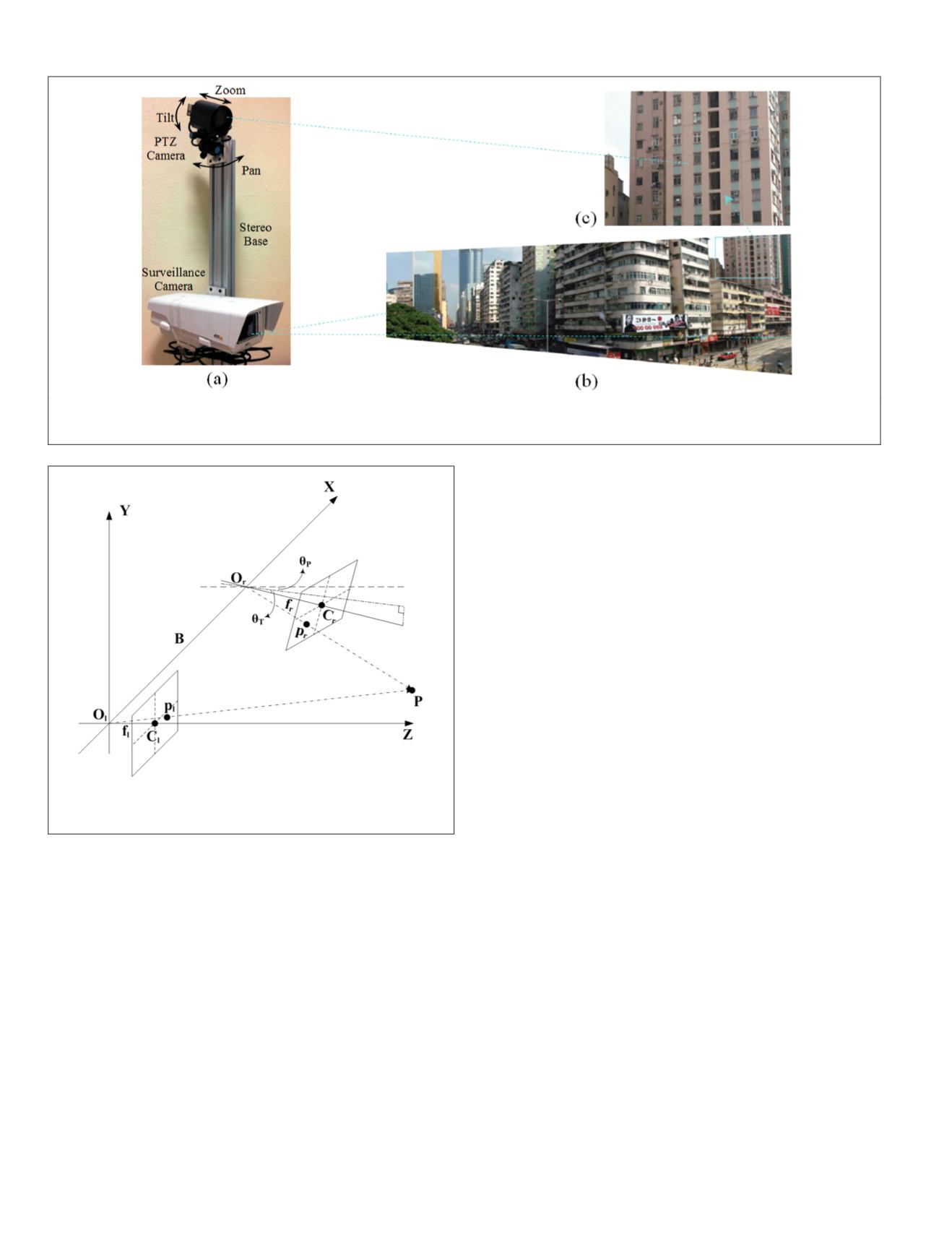
The dual camera system with an asymmetric photogrammet-
ric configuration is illustrated in Plate 1. The configuration
was based on two pin-hole cameras, which worked coop-
eratively in a master-slave configuration. The master camera
(surveillance camera) camera was fixed and had a short focal
length. It monitored a wide
FOV
in the scene to ensure global
surveillance of the area of interest. The slave camera (
PTZ
camera) was actively controlled, and its pan, tilt, and zoom
abilities allowed the generation of close-up imagery of inter-
esting targets. The two cameras were connected through a
vertical rigid base, thus creating a stereoscopic vision system.
In photogrammetry, normally the terms “left” and “right” are
used to distinguish the image pair when processing the stereo
image data. Therefore, in this paper we use the same terms
of “left” and “right” image instead of “bottom” and “top” for
consistency consideration (although the base is vertical). The
term “pan” refers to the rotation of the
PTZ
camera towards or
away from the surveillance camera.
Geometric Modeling of the Asymmetric Photogrammetric Configuration
To describe the geometric configuration of the asymmetric
dual camera system, we have used the pin-hole camera model
(Hartley and Zisserman, 2004) rather than collinearity equa-
tions since the former explicitly incorporates the rotation
angles of the camera system. The system used a local refer-
ence frame centered at the surveillance camera’s perspective
center (see Figure 1). A point
P
= (
X, Y, Z
) in the reference
frame can be projected onto the
PTZ
camera’s image coordi-
nate
p
r
= (
x
r
, y
r
) by using the pin-hole camera model:
n c
s
s
x
y
f s x
f y
r
r
r
r
z
r
z
T
T
λ
θ
θ
=
−
0
0 0 1
0
0 1 0
cos
sin
sin
θ
θ
θ
θ
θ
θ
T
T
P
P
P
P
X
Y
Z
0
1 0
0
0
0
cos
co
in
si
os
−
+
T
, (1)
where
θ
P
and
θ
T
represent the pan and tilt angles of the
PTZ
camera, and (
x
z
, y
z
),
f
r
, and
s
r
, denote its principal point, focal
length, and skew, respectively.
T
denotes the translation vec-
tor between the perspective centers of the
PTZ
camera and the
surveillance camera;
λ
is a non-zero scale factor.
The same point
P
can be projected onto the surveillance
camera’s image coordinate
p
l
= (
x
l
, y
l
) by:
x
y
f s x
f y
X
Y
Z
l
l
l
l
s
l
s
1
0
0 0 1
=
,
(2)
Plate 1. Illustration of the asymmetric dual camera system: (a) A
ptz
camera attached to a regular surveillance camera through a vertical
base, (b) low-resolution image with wide
fov
acquired by the surveillance camera, and (c) zoomed-in image acquired by the
ptz
camera.
Figure 1. Geometric configuration of the asymmetric dual cam-
era system.
220
March 2015
PHOTOGRAMMETRIC ENGINEERING & REMOTE SENSING


