are illustrated in Figure 9b. However, there were systematic
errors in the first strip, in which the checkpoints of the right
part were biased to the southeast direction. In practice, there
were yaw angle errors in the first and the fourth strip, which
caused a planar error decrease with sample coordinates in the
first strip and a horizontal error direction change with sample
coordinates in the fourth strip, as depicted in Figure 8b.
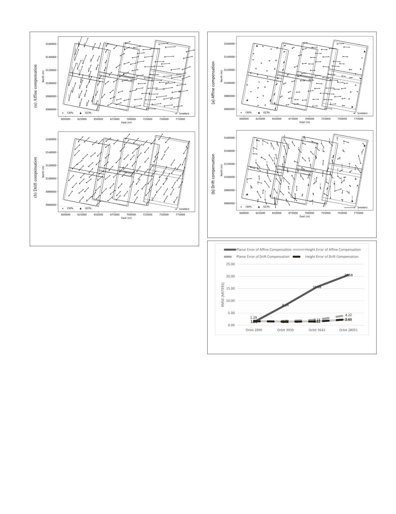
To validate the theoretical precision, only four
GCPs
were
deployed in the first strip. The geolocation errors of each strip
were calculated independently after block adjustment. The
RMSEs
of each strip are illustrated in Figure 10. The planar
RMSE
of affine compensation increased rapidly with the orbit
numbers. For Orbit 28051, the
RMSE
was almost equal to the
RMSE
without
GCPs
, which means that the
GCPs
in the first orbit
had almost no effect on the fourth orbit. The accuracy in Fig-
ure 10 did not strictly obey the laws of theoretical accuracy,
because the
a priori
accuracy of the
RFM
also plays an impor-
tant role in estimating the initial object coordinates of the tie
points. Because of the high accuracy of the remaining three
orbits in height, as shown in Figure 8a, the
RMSEs
of affine
compensation were almost equal to those of the drift compen-
sation. By contrast, the planar
RMSEs
of drift compensation
were much smaller than those of affine compensation. Com-
pared to the accuracy of affine compensation, the accuracy of
the remaining three strips improved significantly, but it was
still reduced with the number of strips. During the deriva-
tion of theoretical precision, it was assumed that there were
no yaw angle errors. In practice, the yaw angle error could be
identified from the first and the fourth strip. Meanwhile, the
lateral overlap in the along-track direction decreased with the
strip numbers. Therefore, the practical accuracy was reduced
by the accumulation of random errors and systematic errors.
The
RMSE
of the entire block was 1.47 m in planimetry
and 1.59 m in height when each strip had four
GCPs
for block
adjustment with affine compensation. With the same
GCPs
,
the
RMSE
of drift compensation was 1.62 m in planimetry
and 1.57 m in height. Because of the compensation for the
yaw angle errors, the affine compensation achieved a slightly
better result than the drift compensation model. However,
after block adjustment with 22
GCPs
, the accuracy difference
between drift compensation and affine compensation was
within 3 cm. In this case, the
RMSE
of drift compensation
was 1.38 m in planimetry and 1.56 m in height, whereas the
RMSE
of affine compensation was 1.35 m and 1.58 m. The
redundant
GCPs
could achieve better accuracy if there were no
significant yaw angle errors, as in Orbit 3939 and Orbit 3642.
This is the reason why two compensation models achieved a
similar accuracy.
Conclusions
Block adjustment is a unified method for simultaneously
determining the orientation of
HRSIs
and improving their
Figure 8. Distribution diagram of geolocation errors of block
adjustment without
GCPs
(the black arrows indicate planar
errors and the gray stand for height errors).
Figure 9. Distribution diagram of geolocation errors of block
adjustment with four
GCPs
in the corners of the entire block.
Figure 10.
RMSE
of strips with four
GCPs
in the first strip,
Orbit 2890.
PHOTOGRAMMETRIC ENGINEERING & REMOTE SENSING
December 2018
797


