above the glacier surface from where a good side view of the
curving glacier is provided, while C2 was placed to look at
the front of the glacier, see Figure 1. Although the cameras are
subject to short term disturbances by buffeting wind, the used
platforms are robust enough for limiting sensor movements.
Data acquisition in both systems started on 17 April 2014,
and lasted until 17 April 2016 (in total, 605 images were
selected and subsequently used for processing). The images
were captured at 12:00 pm local time, generally coinciding
with the highest position of the sun.
Field Support Data
In order to relate the image space to the object space, a num-
ber of primary Ground Control Points (
p
GCPs
) visible within
the camera views (C1 and C2) were surveyed. Dual-frequency
Trimble 5700
GPS
receivers were used to measure 11
p
GCPs
,
seven and four in the
FOV
of C1 and C2, respectively, selected
from a variety of topographic features, including rock outcrops
and erratic blocks since they were static in relation to the
glacier motion during the study period. The
GPS
measurements
were referenced to the CHLT (Chaltén)
CORS
station, located at
El Chaltén. Using
DGPS
static positioning method, the data were
processed using the RtkLib open-source software (Wi
ś
niewski
et al
., 2013), with fixed solutions at the 95 percent confidence
level. The
RMSEs
(root-mean-square error) for the
GCPs
were
N
=
0.01 m,
E
= 0.01 m, and
U
= 0.025 m, respectively.
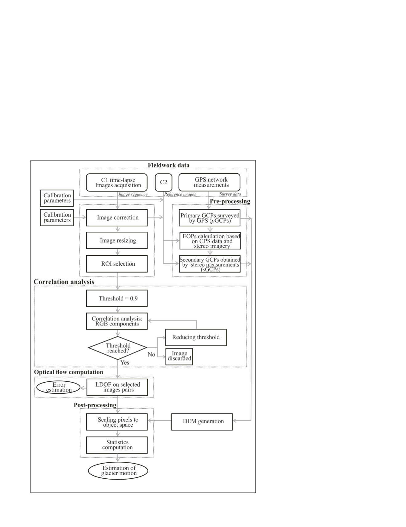
Proposed Method
The overall processing workflow is shown in Figure 2; all the
algorithms and data handling processes were implemented in
Matlab. During preprocessing, the images are prepared and
optimized for the optical flow computation. In addition, us-
ing the calibration parameters, the lens distortion is removed
from the images. In order to reduce computational costs, the
original image size of C1 camera was reduced by about 30 per-
cent based on the actual Region of Interest
(
ROI
); the glacier area was kept and the sky
and background mountain range at the top
of the photos were eliminated. The External
Orientation Parameters (EOPs) for C1 and
C2 cameras were calculated. To add more
ground control data to support the scal-
ing of the optical flow results, in addition
of the surveyed by
GPS
(
p
GCPs
), secondary
GCPs
, obtained by the stereo resection using
images from both cameras, were introduced.
Then, the main processing component, the
optical flow computation method is ex-
ecuted, including the Correlation Analysis
process based on
RGB
components and the
LDOF
computation that also provides the
uncertainty estimation. Finally, as postpro-
cessing, the results were scaled to provide
object space parameters for the glaciological
interpretations.
Image Correction and Orientation
To obtain the highest accuracy of any
derived geospatial product, the imaging
sensor must be calibrated and oriented as
accurately as feasible. Interior and exterior
orientation parameters that model the cam-
era geometry and the relationship between
the camera and object reference systems
must be computed using features previously
matched in both spaces (Garcia Tomaselli
and Lopes Reiss, 2005). How closely the
model conforms to reality will depend on
the model and how well the parameters
of the model can be estimated (Clarke and
Fryer, 1998). The parameters that describe
the physical model of a camera can be
grouped into two categories. The first group,
defined by linear parameters, includes the
focal length, pixel size, and coordinates
of the principal point. The lens distortion
modeling is based on nonlinear parameters,
including multiple parameters. For most
cameras, the radial and, with less impor-
tance, decentering components provide
adequate corrections, and are parametrized
by (
k
1
, k
2
, k
3
)
and (
p
1
and
p
2
) polynomial
coefficients, respectively. Note that lens dis-
tortions could have an increasingly adverse
impact on accuracy with increasing target
distance. In this study, both cameras were
Figure 2. Workflow of glacier surface velocity estimation.
PHOTOGRAMMETRIC ENGINEERING & REMOTE SENSING
January 2018
35


