Corridor Test Site
The important structural distances were measured by a laser
range finder that was accurate to within 1 mm for distance
measurements; these distances are used as the geometric
structural ground truth in our tasks for mapping applica-
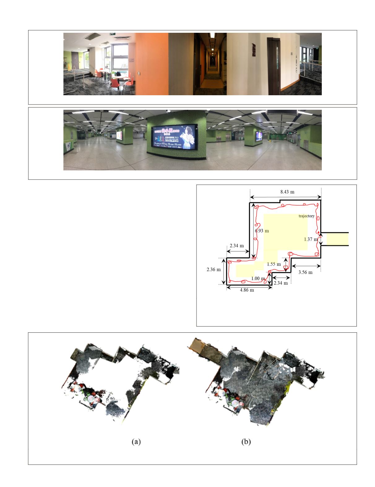
tions. Figure 8 shows the footprint of the corridor dataset
within the geometric structural ground truth measurements.
To assess 3D point cloud accuracy, we used a terrestrial laser
scanner (Leica BLK 360) to capture the corresponding point
clouds. We manually registered those point clouds to act as
the ground truth and then implemented the 3D comparisons.
For Leica BLK 360, the point measurement rate can reach 360
000 points per second with 3D point accuracy within 8 mm,
which is sufficient to assess the gained point clouds from a
low-cost
RGB-D
sensor.
As mentioned, we captured the data along the wall. The
red curve in Figure 8 represents the trajectory of
SLAM
, and
the yellow areas are the regions outside the working scope of
the depth sensor. As Figure 8 shows, we designed some small
loops in the trajectory to capture more
RGB
image sequences
from the yellow areas. Figure 9a shows the
SLAM
point cloud
model in this case, and Figure 9b presents the integrated
model (i.e., the image-based model registered to the
SLAM
Figure 6. Corridor test site.
Figure 7. Subway station test site.
Figure 8. Floor plan of the corridor within the reference
geometric information and the strategies of the designed
experiment. The red line is the
SLAM
trajectory, and the
yellow areas are outside the depth camera working range.
Figure 9. 3D mapping results. (a)
SLAM
point cloud model; (b) Registered point cloud model; that is, the
SLAM
model + the
imaged-based model.
PHOTOGRAMMETRIC ENGINEERING & REMOTE SENSING
September 2019
637


