transformation and path opening operation.
In the second step, a Bottom-Hat transformation is applied
to extract dark structures from the background. Bottom-Hat
of an image is the difference between the morphologically
closed image and the original image. The formula of Bottom-
Hat transformation can be represented as (Soille, 2003):
BOTHAT
(
f
) = (
f · g
) –
f
(3)
where
f
is the original image, and
g
is the selected structuring
element (a pre-defined small binary image) used to probe the
original image, operator ‘∙’ stands for closing operation. The
size of the structuring element for the morphology closing
operation greatly affects the final result; the larger the size of
structuring element is, the more the dark features are pre-
served. Increasing the number of preserved features makes
more gullies to be detected, but may also results in more spu-
rious gullies. A square structuring element with a size of 11
× 11 pixels is set for the Bottom-Hat transformation, for this
size is close to the width of most gullies in pixels. According
to the convention, a square structuring element is always a
binary image with all pixels being the value 1. The features
extracted by Bottom-Hat transformation of the filtered image
of Figure 3a are shown in Figure 4. The resultant grayscale
image is reversed and stretched for better visualization. Most
of the background is removed, with gullies and many other
small dark features remain preserved.
The third step of the morphological image analysis is
removing non-gully features from the Bottom-Hat transfor-
mation result by path opening operation. Path opening was
first proposed by Buckley and Talbot (Buckley and Talbot,
2000); Heijmans
et al
. (2004 and 2005) explained its theoreti-
cal foundation thoroughly, and it has been further improved
by Luengo Hendriks (2010). Path opening is a morphologi-
cal transformation using flexible line segments structuring
elements, in which the line segments have a general direc-
tion and they can rotate and bend in a certain extent due to
their flexibility. The transformation searches paths in four
directions, namely 0°, 45°, 90°, and 135°, allowing the paths
to deflect inside a 90° aperture centered in each of the four
directions to detect lines that are not strictly straight. The
transformation has been proved effective in extracting linear
objects in satellite images, such as roads and dust devil tracks
(Valero
et al
., 2009; Statella
et al
., 2012). The minimum length
L
of the searched paths is a parameter that greatly affects the
final result, as those paths shorter than
L
will be filtered out.
In our experiments,
L
is set as 300/
R
empirically, in which
R
is the image resolution. The path opening operation is per-
formed using the image processing library of “DIPlib” devel-
oped by Luengo Hendriks (2010). After path opening, pixels
with nonzero grayscale values are considered to belong to
gully channels and a binary image is generated by setting all
nonzero grayscale values to 1. Connected component extrac-
tion (Haralick and Shapiro, 1992) is performed on the binary
image to get the final result of gully detection, in which one
connected component is considered as one gully.
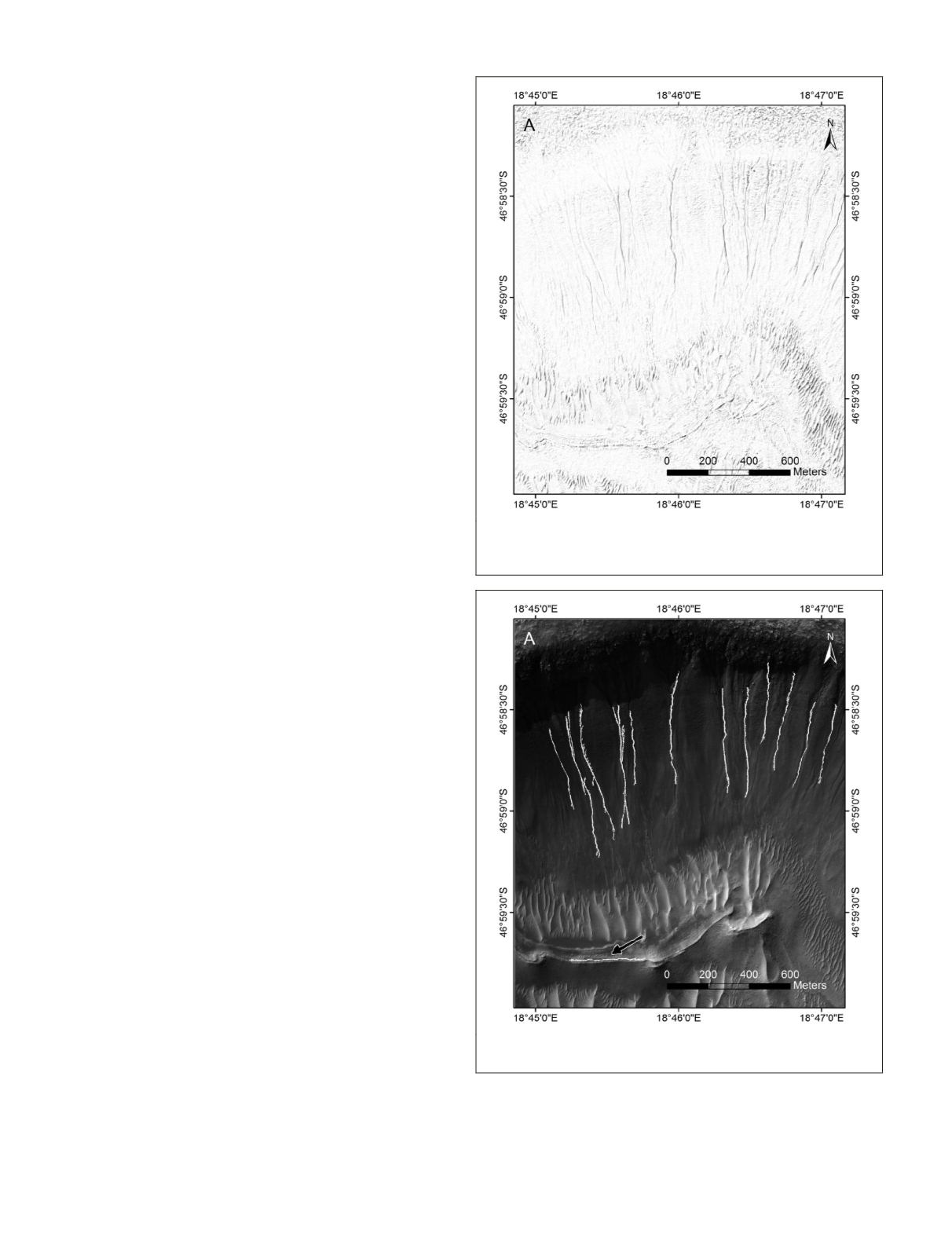
Figure 5 shows the gully detection result overlapped on
the original image. Most gullies are detected correctly, but one
spurious gully, which is a small sand ripple, is also extracted.
This false detection is difficult to eliminate by image analysis
only, thus the
DTM
data, if available, is introduced to improve
the detection result.
Considering that Martian gullies are always located on
steep slopes, the detection result can be refined by relief
calculation using
DTM
data. This operation handled each con-
nected component in the binary image by the following steps:
1. Find the pixels with maximum and minimum eleva-
tion values in the connected component;
2. Compute the straight-line distance
D
and the elevation
difference
dH
between the two pixels;
3. Remove the component if arctan (
dH
/
D
) <
θ
.
Figure 4. Result of Bottom-Hat transformation of the filtered im-
age of Figure 3a. The resultant image is reversed and stretched
for better visualization.
Figure 5. Result of gully detection through morphological operations
of the image in Figure 3a. The arrow indicates a spurious gully.
916
December 2015
PHOTOGRAMMETRIC ENGINEERING & REMOTE SENSING


