System Design and Calibration
The image-based mobile mapping system (
MMS
) of the
FHNW
is being developed since 2009. It has evolved into a multi-ste-
reo camera system mainly used for demanding road and rail
infrastructure mapping and management projects (Burkhard
et al
., 2012). Our novel camera configuration approach allows
for a complete 360° stereo image acquisition in heavily built-
up urban environments. A forward looking and a backward
looking stereo system, consisting of wide-angle pinhole cam-
eras, cover the road with its infrastructure. In addition, two
multi-head panoramic cameras tilted forward and backward
by 90° each complete the configuration (see Figure 3). The
individual heads of the panoramic cameras facing perpen-
dicular to the driving direction build multiple stereo systems,
which cover pavement, entire façades of buildings and the en-
tire overhead space even in challenging urban environments.
Figure 3. Novel configuration featuring several stereo
camera systems for 360°
RGBD
mapping.
System Description
Our
MMS
features a NovAtel SPAN inertial navigation system
with a tactical grade
IMU
of the type UIMU-LCI and a L1/L2
GNSS
kinematic antenna. In case of good
GNSS
coverage, these
sensors provide a precision of horizontally 10 mm and verti-
cally 15 mm during postprocessing (NovAtel, 2012). Accura-
cies of the attitude angles roll and pitch are specified with
0.005° and heading with 0.008°.
Our
MMS
camera setup consists of three different camera
types. Both industrial cameras (AVT & Basler) equipped with
wide-angle lenses are suitable for creating stereo camera
systems with fixed baselines. The large sensor pixel size (see
Table 1) results in low-noise images. Ladybug5 panorama
cameras consist of five individual heads facing sideways as
well as one camera head pointing upward. Each camera head
has a resolution of five megapixels, and features ultra-wide-
angle (fisheye) optics.
Table 1. Interior orientation parameters of the cameras in our
setup.
Camera
type
Resolution
[px]
Pixel size
[µm]
Focal
length [mm]
Field-of-view
[deg]
AVT 4008 × 2672 9.00
21.0
81 × 60
Basler
1920 × 1080 7.40
7.9
84 × 54
Ladybug 5
camera head
2448 × 2048 3.45
4.3
113 × 94
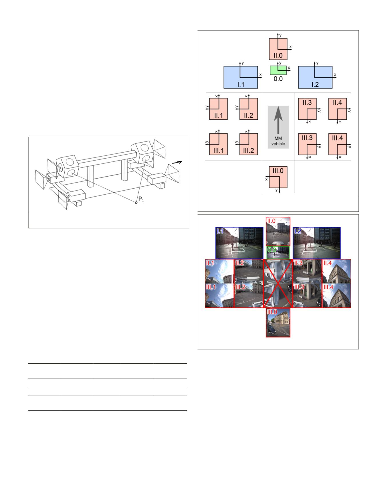
For the following investigations, we configured our
MMS
with two tilted panoramic heads (II & III) and a single
forward-looking stereo camera system (I) (see Figure 4). We
mounted an additional Basler camera (0.0) in the center of the
forward-looking stereo camera system (see Figure 4) for fur-
ther investigations, which we will not discuss in this paper.
Figure 4. Outline of our camera setup showing the definitions
of image coordinate systems for calibration and processing.
Figure 5. Images captured by all cameras at the same location.
In our tilted scenario, the two top camera heads of each
Ladybug5 panorama camera face either forward or backward
(see Figure 4, II.0 and III.0). The five heads pointing sideways
constitute five stereo systems. However, the stereo system
looking downward to the
MMS
vehicle is omitted (see Figure
5). Consequently, we further processed the following stereo
camera systems: forward with a base length of 905 mm, left-
up, left-down, right-down, and right-up with baselines of
1,584 mm (see Table 2). Figure 4 depicts the modified defini-
tions of image coordinate systems of the individual Ladybug5
heads, which we subsequently used for calibration and image
processing.
PHOTOGRAMMETRIC ENGINEERING & REMOTE SENSING
June 2018
349


