Table 2. Overview of all stereo systems.
Stereo
system
Camera
type
Left
camera
Right
camera
Base length
[mm]
Forward AVT
I.1
I.2
905
Left-up
Ladybug 5 III.1
II.1
1584
Left-down Ladybug 5 III.2
II.2
1584
Right-down Ladybug 5 II.3
III.3
1584
Right-up Ladybug 5 II.4
III.4
1584
Figure 6. Indoor (left) and outdoor (right) calibration fields
for our mobile mapping system.
Calibration
The required system calibration of our
MMS
consists of three
tasks:
• calibration of the interior orientation parameters (
IOP
) for
each single camera,
• calibration of the relative orientation parameters (ROP)
between the left and right cameras of each stereo system,
and
• boresight alignment (
BA
) in order to determine lever arm
and misalignment between the left camera of each stereo
system and the reference frame of the navigation system
Burkhard
et al
. (2012) implemented a constrained multi-system
calibration software based on the bundle adjustment approach
according to Ellum and El-Sheimy (2002) and developed the
standard calibration procedure of our
MMS
. We extended the
calibration software with fisheye camera support using the equi-
distant camera projection model (Abraham and Förstner, 2005).
For the system calibration, we installed both an indoor and
an outdoor calibration field (see Figure 6). Our indoor calibra-
tion field features 188 well-distributed target points on all
four walls as well as on the ceiling. We measured the target
points with a contactless high-precision industrial measure-
ment system, thus the standard deviation of a target point is
below 0.3 mm. In contrast, our outdoor calibration field is
located on a basketball court and has fewer target points but
good
GNSS
coverage. We measured both natural (e.g., corner
points on the court) and artificial target points (e.g., fixed on
candelabra) by a total station resulting in standard deviations
of a few millimeters.
In order to perform the calibration, we subdivided the
BA
into two parts; part one is defined by the left camera of
the front stereo system (I.1) to every left camera of a stereo
system; part two is the
BA
between the navigation center and
camera I.1. Figure 7 depicts a summary of our
MMS
calibration
procedure.
First of all, we estimated the
IOP
,
ROP
, and
BA
part one in
our indoor calibration field (see Figure 8). We performed this
calibration step with eight image epochs at different locations
by triggering all cameras at the same time.
The front camera system (I.1 & I.2) and camera 0.0 are
pinhole cameras following the perspective projection model.
Schmeing
et al.
(2011) modeled Ladybug3 panorama camera
images as virtual spherical images. Rau
et al
. (2016) ap-
plied the same model to the Ladybug5 panorama camera as
described in the Ladybug5 technical reference (Pointgrey,
2013). Since we model each single camera head separately, no
stitching error will occur. Our camera calibration investiga-
tions showed that the equidistant projection model (Abraham
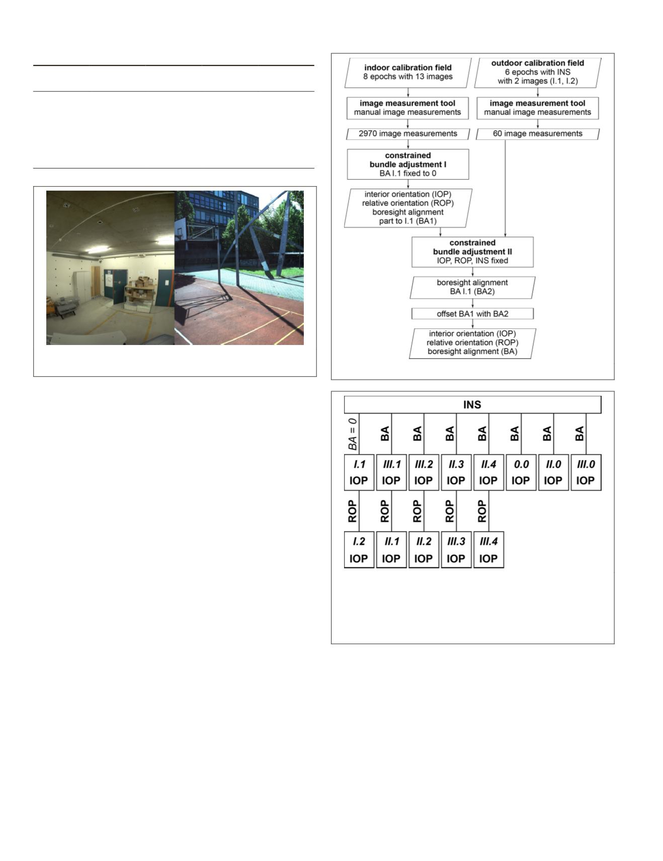
Figure 7. Workflow of our
MMS
calibration procedure.
Figure 8. Functional model of the constrained bundle
adjustment (I) for indoor calibration. We estimated the bold
parameters (
INS
corresponds to the exterior orientation of
camera I.1 in this case), we fixed the italic parameter (BA
= 0) to zero, and we introduced image observations of the
bold italic camera heads into the computation.
350
June 2018
PHOTOGRAMMETRIC ENGINEERING & REMOTE SENSING


