position and attitude with the respective distances measured
by the laser unit. Adler
et al.
(2014) developed an
ALS
embed-
ded on a multirotor helicopter (Okto 2), applied for urban
environments, and presented a rigorous approach for online
synchronization with a precision of 1 ms. Torres and Tom-
maselli (2018) tested the applicability of a lightweight
ALS
aboard a
UAV
, focusing on forest areas and biomass estima-
tion. Time stamps for scanner synchronization via pulse-per-
second and National Marine Electronics Association format
were sent by the navigation system (NovAtel
SPAN-IGM-S1
) to
the Ibeo
LUX
laser scanner, achieving a synchronization error
of approximately 1 ms.
These works used real-time synchronization, which re-
quires a specialized electronic that can fail during data acqui-
sition. The challenges can increase with low-cost
ALS
systems
because some device connections are less stable and more
prone to errors. Despite the recognized importance of time
synchronization for
UAV
-
LS
data usability, few studies have
proposed postprocessing synchronization techniques (Kuh-
nert and Kuhnert 2013; Glira, Pfeifer and Mandlburger 2016),
especially for failure cases when the clock differences were
not minimized in real time due to device communication
problems. This article presents a postprocessing synchroniza-
tion technique to estimate the clock differences between the
GNSS
receiver and the laser-unit, based on the correlation be-
tween the ranges (acquired by the laser unit) and altitudes (ac-
quired by
GNSS
), followed by refinement with a least-squares
method (
LSM
) and boresight-angle correction. The proposed
approach includes a data-acquisition step with special flight
maneuvers, planned to produce altimetric variations in the
UAV
trajectory that are used to compare the signals generated
by the ranges. Experimental assessments using a lightweight
UAV
-
LS
system composed of decoupled devices were per-
formed to evaluate the feasibility of the proposed technique
.
UAV Laser Scanning System
A lightweight
UAV
laser scanning system was used in this
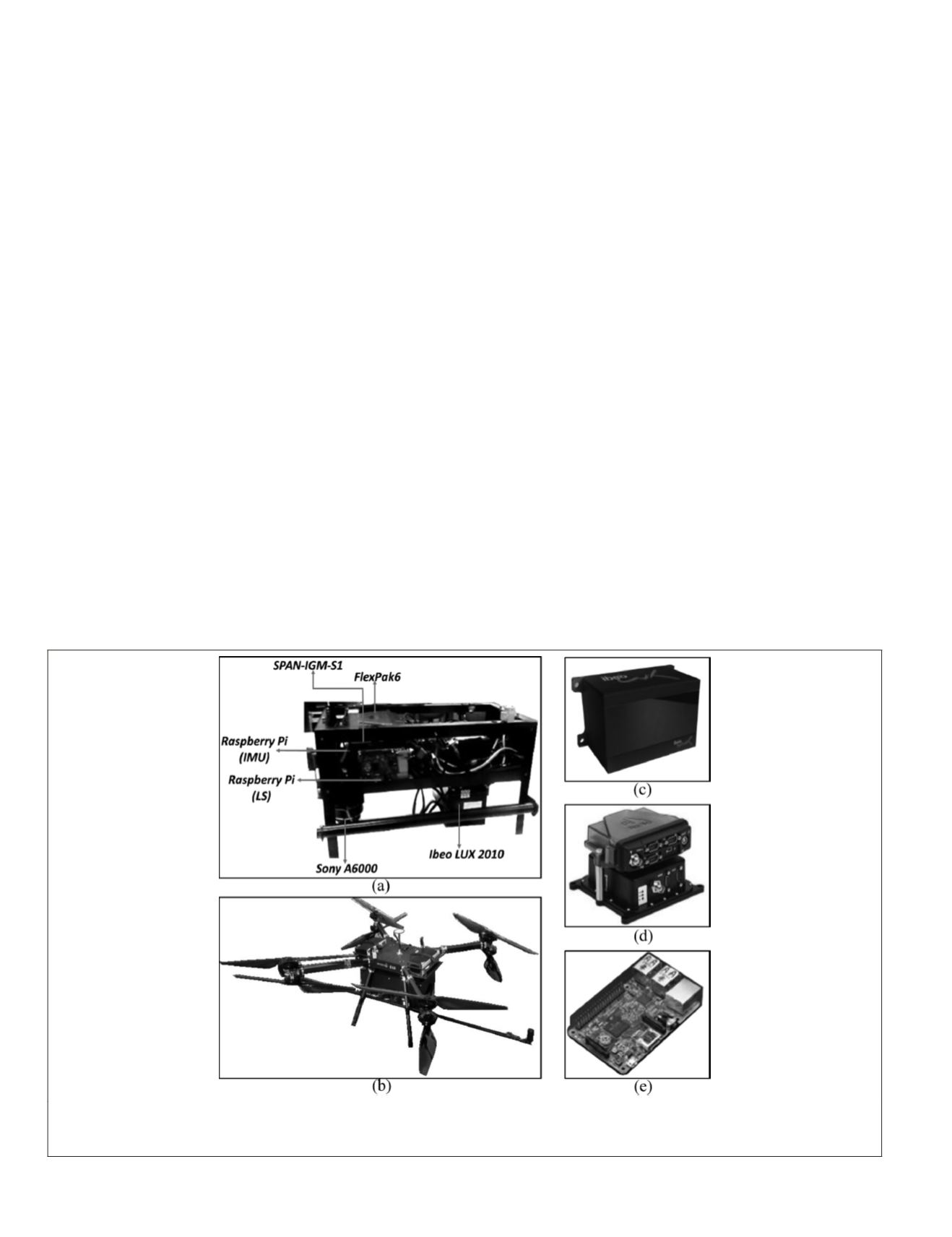
research (Figure 1). This section summarizes the devices and
integration procedure used. The main components of an
ALS
are a laser scanner unit and a navigation system, integrating a
GNSS
receiver and an
IMU
.
The laser unit used (Figure 1c), the Ibeo
LUX
2010 (Ibeo
Automotive Systems, Hamburg, Germany), was initially de-
veloped for wheeled-vehicle guidance. The main advantages
of this sensor are its lightweight (<1 kg), compact structure
(164.5 × 93 × 88 mm), low cost, and high measurement range
(0.3–200 m). The Ibeo
LUX
2010 is composed of two laser
emitters and four independent aligned receivers. Thus, dis-
tance and direction measurement of objects is performed
with four scan levels (laser-beam emissions). These levels
are scanned interlaced, which means that two scan levels are
scanned simultaneously (Ibeo Automotive Systems 2010).
Measurements are performed with a horizontal field of view
of 85° (35° to −50°) and a vertical field of view of 3.2° (+1.6° to
−1.6°). The nominal ranging resolution is 4 cm for terrestrial
application; however, assessments considering
UAV
platforms
such as those presented by Jaakkola
et al.
(2010) and Torres
and Tommaselli (2018) have shown an average altimetric ac-
curacy of 10 cm. Ibeo
LUX
2010 raw data are provided in .idc
format and can be converted to .csv format with a Python
script provided by the manufacturer. The original Python
script was modified to select only the raw lidar data of inter-
est for this research (point ID, scanning level, echoes, time,
distance, angles, and pulse width).
The navigation system (Figure 1d) is the NovAtel
SPAN-IGM-
S1
, which integrates a dual-frequency
GNSS
receiver (NovAtel
OEM615
), a microelectromechanical
IMU
(Sensonor STIM300),
and a second
GNSS
receiver (NovAtel FlexPak6) for head-
ing improvement. Two microcomputers (Raspberry Pi) were
used for data integration and storage (Figure 1e), enabling
Figure 1. Hardware: (a) aluminum container with the sensors; (b) airborne laser scanning system aboard an unmanned aerial
vehicle and the global navigation satellite system antennae mounted in a metallic bar; (c) Ibeo
LUX
2010 laser scanning unit;
(d)
SPAN-IGM-S1
inertial navigation system and FlexPak6 receiver; (e) Raspberry Pi microcomputer model.
754
October 2019
PHOTOGRAMMETRIC ENGINEERING & REMOTE SENSING


