independent records for the laser-unit data and raw naviga-
tion data (
GNSS
receivers and microelectromechanical
IMU
).
The Ibeo
LUX
2010 and navigation-system devices were
arranged in a payload carried by
UAV
octocopter (Sensormap
Sx8, Figure 1b). The laser unit was positioned below the
structure. The other devices—including the NovAtel
SPAN-
IGM-S1
, FlexPak6 receiver, Raspberry Pi microcomputers, con-
nection cables, and battery—were placed inside of the alumi-
num container (Figure 1a). A single-frequency
GNSS
receiver
(NavSpark
NS-RAW
) and the
GNSS
antennae were arranged at a
1-m bar (Figure 1b). After physical device integration, the sys-
tem mounting parameters can be obtained by direct laboratory
measurement and a calibration process, which is described
later under Calibration of the
ALS
.
Postprocessing Synchronization
A technique to perform off-line time synchronization that
compares signals generated by decoupled devices from an
ALS
acquisition for low platform speed (<5 m/s) is presented
in this section. Off-line synchronization can be defined as a
technique that enables the association between sensor posi-
tion estimated by
GNSS
(
GPS
time and
GNSS
height) and lidar
data (laser local time and distance) in a postprocessing step to
estimate the clock differences of these devices and, from these
differences, assign the
GPS
time to the corresponding lidar
data. The proposed technique requires the following steps: (1)
UAV
maneuvers at the beginning and ending of the flight (see
Flight Maneuvers and Data Acquisition); (2) computation of
the clock differences and off-line synchronization by cross-
correlation (see Clock-Difference Estimation and Off-Line
Synchronization); (3) data-synchronization improvements
with
LSM
(see Refinement by the Least-Squares Method); and
(4) estimation of boresight misalignment of the laser unit
with respect to the
IMU
(see Calibration of the
ALS
). The main
contributions of the new synchronization approach presented
in this article rely on the processes described under Clock-
Difference Estimation and Off-Line Synchronization and
Refinement by the Least-Squares Method. The flight maneu-
vers during
ALS
data acquisition enable flexible
ALS
data col-
lection with further processing without the need for real-time
synchronization, either in case of failu
synchronization is unfeasible or diffic
Flight Maneuvers and Data Acquisition
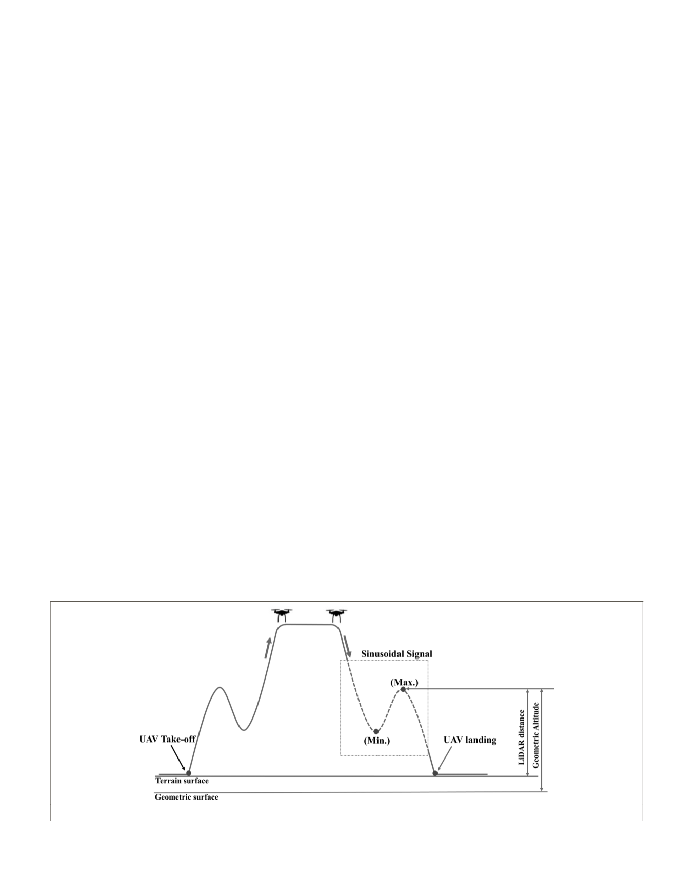
The concept of off-line synchronization proposed is based
on
UAV
flight maneuvers to generate a signal that enables
comparison between the laser ranges and
GNSS
altitudes. The
flight maneuvers follow a trajectory with height variations
in a sinusoidal shape just after takeoff and before landing.
Therefore, the laser ranges and
GNSS
altitude measurements
generate similar signals, as exemplified in Figure 2. A flight
maneuver over flat and non-vegetated terrain is suggested to
ensure a better comparison between laser and
GNSS
signals.
Significant terrain slope can result in systematic errors in the
synchronization with the proposed technique.
These flight maneuvers generate maximum and minimum
height points in a sequential data acquisition. The matching
between signals (ranges and altitudes) can be performed by
manually or automatically identifying the maximum (Max.)
and minimum (Min.) height points (Figure 2), comparing the
complete sinusoidal signals of the trajectory. This comparison
is used to estimate the clock difference. The automatic option
is investigated and assessed in this article.
Clock-Difference Estimation and Off-Line Synchronization
The proposed method considers that homologous signals (Figure
2) have similar heights (
GNSS
flight height and lidar range) but
different time reference systems (
GPS
time and local laser time).
The synchronization process comprises four steps: (1) prelimi-
nary processing, (2) height- and lidar-data resampling, (3) estima-
tion of the clock difference, and (4) correction of the laser time.
1. The lidar data from the Ibeo
LUX
laser scanner are stored
as sequential packages, which contain information from
four levels of scanning during a data-collection period
(see earlier, under
UAV
Laser Scanning System). Time
information is present only at the beginning and end of
each packet. Therefore, a time interpolation is necessary to
associate a local laser time with each measurement. After
laser-time interpolation, the data set was clipped to obtain
only the corresponding sinusoidal signals of the trajectory
on the lidar data, which is used as a reference vector to
search the maximum correlation with the
GNSS
data.
2. Lidar data (distance) and
GNSS
data (geometric altitude)
were converted to flight heights, which enable comparison
between the sinusoidal signals from the lidar ranges and
GNSS
altitude. The flight heights are referenced to the ter-
rain surface (origin), which is comparable to the distance
between the ground and the sensor. The
GNSS
altitude was
he geodetic coordinate to a flight height
sidering the altitude of the test area
ch was measured by the
GNSS
receiver
gure 2). The lidar data were selected ac-
cording to the vertical and horizontal angles to obtain the
shortest distance between the laser unit and the terrain
Figure 2. Maneuvers for data acquisition with the airborne laser scanning devices aboard the unmanned aerial vehicle.
PHOTOGRAMMETRIC ENGINEERING & REMOTE SENSING
October 2019
755


