al, 2011; Poli and Toutin 2012; Jiang
et al.
2014; Y. Zhang
et
al.
2014; Cao, Yuan and Gong 2015; Wang
et al.
2017). The
traditional calibration methods for an optical-satellite camera
commonly involve both external and internal calibration
(Wang
et al.
2014; G. Zhang
et al.
2014; Chen
et al.
2015).
External-parameter calibration refers to determining the exter-
nal installation angles of the camera, while internal-parameter
calibration refers to determining the internal distortion of the
camera. Depending entirely on the calibration field, the abso-
lute and relative geometric positioning accuracy of the optical
remote sensing images can be guaranteed by the traditional
calibration methods. In order to have a total constraint for the
whole charge-coupled device (
CCD
) of the camera, the high-
accuracy calibration field that covers the image swath entirely
is necessary for traditional calibration methods. However,
building and maintaining a high-accuracy calibration field
with larger coverage will be more expensive and labor-in-
tensive. The demand for each
WFV
camera to provide images
with more than 200 km of coverage is even more challenging,
particularly due to changes in the surface texture of the cali-
bration field due to seasonal variation. Therefore, in order to
reduce the dependency on the high-accuracy calibration field,
researchers are exploring on-orbit self-calibration methods.
The relative geometric relationship of the overlapped im-
ages is usually used for camera self-calibration in close-range
and aerial photogrammetry (Faugeras, Luong and Maybank
1992; Maybank and Faugeras 1992; Fraser 1997; Malis and Ci-
polla 2002; Gonzalez
et al.
2013). However, most research has
been aimed at the area array camera (Malis and Cipolla 2002;
Wang
et al.
2018), which is hardly applicable to the linear-
array push-broom imaging system on the optical remote sens-
ing satellite. Though self-calibration block adjustment is one
common method of calculating camera parameters (Habib,
Morgan and Lee 2002; Kocaman and Gruen 2008; Di
et al.
2014; Zheng
et al.
2015), the long-period data-acquisition
time and unstable calibration accuracy are the major draw-
backs. The Pléiades satellite made its self-calibration based on
active cross-imaging (Greslou and Delussy 2006; de Lussy
et
al.
2012; Delvit
et al.
2012; Kubik 2012; Pi
et al.
2017), which
is still hard for the
GF1
satellite. Cheng and colleagues (2018)
proposed a self-calibration method for a multilinear array
with a small field of view, but the
WFV
c
satellite have only one linear array, with
In this study, we developed a new ge
approach for
WFV
cameras based on a pa
tion field. It significantly reduces the demand for the refer-
ence calibration field with large coverage, and thus is much
more labor- and cost-saving. We selected two or three ste-
reoscopic images within an appropriate overlapping region.
The single
CCD
in the
WFV
camera was divided into two parts,
one shorter (primary
CCD
) and the other longer (secondary
CCD
). Based on the small calibration field, the primary
CCD
was calibrated first, which was used to provide the necessary
relative reference camera coordinate systems for the following
self-calibration of the whole
CCD
detector system.
We present two self-calibration models and corresponding
parameter-estimation methods for the
WFV
cameras of the
GF1
satellite based on partial calibration-field coverage. Our exper-
imental results indicate that the internal relative accuracy can
be greatly increased by the proposed self-calibration scheme.
Thus, we present a novel approach for the calibration of a
single-linear-array push-broom satellite, with few calibration-
field limitations.
Rigorous Imaging Model of a WFV Camera
A rigorous geometric imaging model incorporates both satel-
lite auxiliary data and camera parameters and serves as the
foundation for an on-orbit calibration model (Jiang
et al.
2014;
Wang
et al.
2014; Cao
et al.
2015; Cheng
et al.
2017). From the
on-orbit calibration, each single camera can be described by
X
Y
Z
X
Y
Z
g
g
g
WGS84
s
s
s
=
time
time
time
(
)
(
)
(
)
WGS84
J2000
WGS84
body
J2000
camera
body
+
λ
ψ
ψ
R R R
x
y
tan
tan
1
. (1)
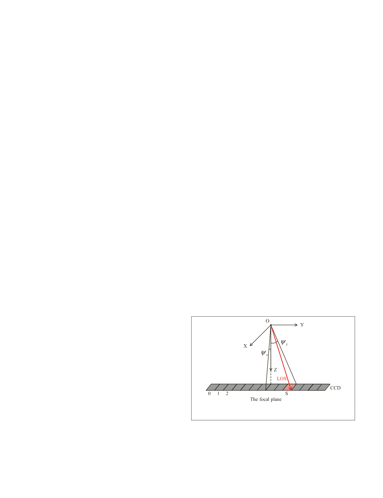
The
LOS
(shown in Figure 2) [tan
ψ
x
tan
ψ
y
1] of the image
point (
s,l
)
i
in a single-camera coordinate system (O-XYZ) can
be described by
tan
tan
ψ
ψ
x
y
a a s a s a s a s a s
b b s b s b s b s
= + + + + +
= + + + +
0 1 2
2
3
3
4
4
5
5
0 1 2
2
3
3
4
4
5
5
+
b s
,
(2)
Where
a
0
,
a
1
,
a
2
,
a
3
,
a
4
,
a
5
,
b
0
,
b
1
,
b
2
,
b
3
,
b
4
, and
b
5
are the
coefficients of the interior
LOS
of the
CCD
detector in the
WFV
camera;
i
=
WFV1
,
WFV2
,
WFV3
,
WFV4
; (
s,l
)
i
is the image coor-
dinates; [
X
g
Y
g
Z
g
]
WGS84
are the WGS84 coordinates of the
corresponding ground point; [
X
S
(time)
Y
S
(time)
Z
S
(time)]
T
is
the position vector of the center of projection of the WGS84
coordinate system;
R
body
camera
(roll, pitch, yaw) is the installation
matrix from the camera coordinate system to the satellite-body
coordinate system; roll, pitch, and yaw are the installation
angles;
R
J2000
body
is the attitude matrix from the satellite-body co-
ordinate system to the J2000 coordinate system, which can be
interpolated from the attitude observation;
R
WGS84
J2000
represents
the attitude matrix from the J2000 coordinate system to the
WGS84 coordinate system;
λ
is a scale factor; and time is the
imaging time. Because of the complete correlation between the
internal
LOS
and the external installation angles, traditional
calibration approaches based solely on the absolute constraint
of the calibration field generally use a stepwise parameter-es-
timation strategy. External calibration parameters (roll, pitch,
and yaw) should be calculated first, and then the internal
(
a
0
,…,
a
5
,
b
0
,…,
b
5
) are calculated based
ate system determined by the external
(installation angles; Wang
et al.
2014).
Figure 2. Diagrammatic sketch of the line of sight in the
camera coordinate system.
The On-Orbit Geometric Calibration Approach
This section shows the basic process flow of the proposed
geometric calibration approach. After that come two self-
calibration models used in the proposed calibration ap-
proach: the model based on elevation residual error (using
816
November 2019
PHOTOGRAMMETRIC ENGINEERING & REMOTE SENSING


